Information Technology Reference
In-Depth Information
a
i+
1
b
i+1
i+2
i
+2
i
i
β-strand 1
β-strand 2
β-strand 1
β-strand 2
Figure 10. Type I (a) and type II (b) β-Turns. The
i+
1 residue in Type I is reversed
in type II.
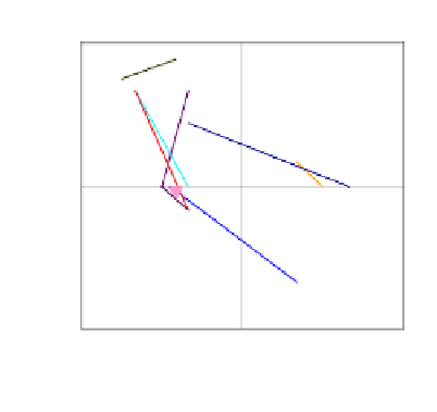
180
VIb
135
VIa1
Figure 11. Average φ and ϕ values for
residue 2 connecting to average φ and ϕ
values of residue 3 for β-turns. The
arrowheads denote the residue 3
90
II
V III
45
VIa2
φ
and
ϕ
I'
ϕ
0
values (Adapted from Guruprasad &
Rajkumar, [27])
I
-45
II'
-90
-135
-180
-180 -135
-90
-45
0
45
90
135
180
φ
The fourth type of turn, the
α
-turn, contains five residues which may be stabilised
by a hydrogen bond between the backbone CO(i) and the backbone NH(i+4) [28] although
other hydrogen bonding patterns are possible. Nine types have been categorised according
to the
angles of the second, third and fourth residues.
The largest tight-turn is the
π
-turn with six-residues stabilised by a hydrogen bond
between backbone CO (i) and the backbone NH (i+5). Generally
φ
and
ϕ
π
turns are found at the C-
termini of
-helical conformation
(
π
αL
). Three other classes of
π
turn have been identified [29]. These are the
π
αR
turn, and
the
α
-helices with the fifth residue adopting left-handed
α
π
β
turn in which the fifth residue
φ
and
ϕ
angles are in the
α
R
and
β
regions of the
Ramachandran map respectively, and the
π′
αL
turn which is the mirror image of the
π
αL
turn.
2.4 Identifying Secondary Structure
How are crystal structures analysed to find regions of secondary structure which correlate
to the preceding 'text book' descriptions? Before the advent of accessible computer
technology secondary structures were identified from visual inspection of atomic models,
observing the local conformation of residues relative to those nearby and ascertaining
hydrogen bond patterns between closely spaced amides. This method tends to be subjective