Civil Engineering Reference
In-Depth Information
a
b
c
d
e
f
g
h
i
j
k
l
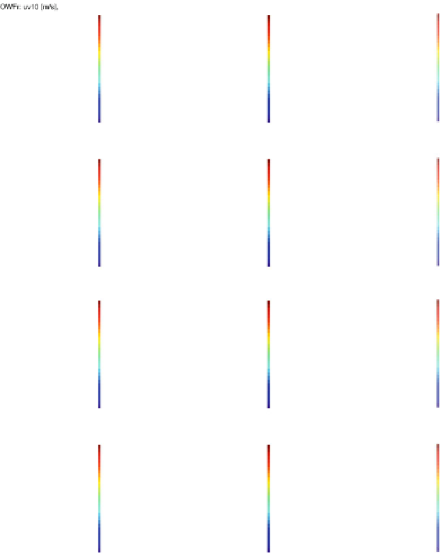
Fig. 4.7 Variations in the 10-m wind field due to different OWF operation mode of a 12-turbine
OWF. Illustrations (a)-(j) show the development of the real (run OWFr) METRAS 10-m hori-
zontal wind field for different time steps and OWF operation cases. The first wind farm is off (a)
then is switched on (b), and turbines operate, which means METRAS wind turbine parameteriza-
tion is considered (c-e). Later, OWF is switched off again (g). Turning off the OWF ends in
advection of wind wake with the main wind field (h-l). Be aware of the different color bar in (a).
The METRAS simulation times
t
are listed in the header of each picture


Search WWH ::

Custom Search