Biomedical Engineering Reference
In-Depth Information
the beam number change. The total number of beams for the standard IVUS
equipment is normally between 240 and 360 beams [24].
1.6.4 Real versus Simulated IVUS
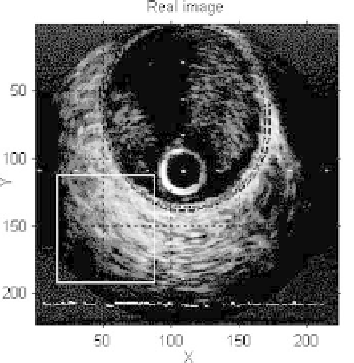
In order to compare the real and simulated IVUS images, we have generated 20
synthetic images with morphological structures corresponding to the structures
of a set of real images. We have used a real IVUS image with manually delimited
lumen, intima, and adventitia to obtain the average radius location
R
k
for each
arterial structure. We applied the optimal frequency of 46 MHz and attenuation
coefficient of 0
.
8 dB/MHZ cm. Figure 1.32(a) shows an IVUS real image of right
coronary artery, obtained with a 40 MHz Boston Sci. equipment. Figure 1.32(b)
shows a simulated image obtained at the optimal ultrasound simulation fre-
quency of 46 MHz. In the real image, we can observe a guide zone artifact (12
to 1 o'clock) due to the presence of guide; this artifact will not be simulated
in this study. The horizontal ECG baseline appears as an image artifact on the
bottom of the real image. The global appearance of each image region (lumen,
intima, media, and adventitia) and its corresponding interface transitions (lu-
men/intima, intima/media, and media/adventitia) are visually well contrasted,
compared to the real image. A good quantitative global measure for comparison
Real image
Simulated image
(a)
(b)
Figure 1.32:
Real (a) and simulated (b) IVUS images segmentation. ROIs are
given as squares. Manual segmentation of the vessel is given in (a).