Biomedical Engineering Reference
In-Depth Information
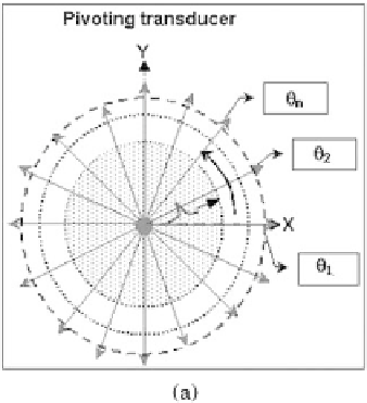
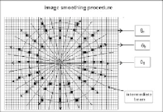
Figure 1.23: The transducer emits from the artery center (a), echo profile trans-
formed into penetration depth (b), the echo profiles are transformed to a polar
image (c), and empty pixels filled and the final IVUS image is smoothed (d).
image, and the intermediate beams are computed (Fig. 1.23(c)). The image is
transformed to Cartesian form and the empty pixels are filled (Fig. 1.23(d)).
Using the ultrasound reflected signal
S
(
t
,
) for a finite set of
N
reflecting
scatterers with coordinates (
R
,,
Z
) and spatial distribution of the differen-
tial backscattering cross-section,
σ
(
R
,,
Z
), the 2D echo signal
S
(
t
,
) can be
written as:
N
θ
i
N
R
σ
(
R
i
,
±
θ
j
)
ζ
(
t
,δ
i
)
|
R
i
|
S
(
t
,
)
=
C
o
(1.15)
i
=
1
j
=
1
where
S
(
t
,
) is the temporally generated signal by a set
N
R
of scatterers, which
are localized in angular position
θ
,
θ
∈
[
θ
a
,θ
b
],
N
θ
i
is the total scatterers number