Biomedical Engineering Reference
In-Depth Information
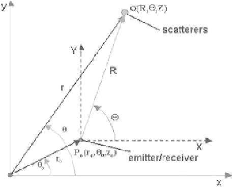
Figure 1.6: Coordinates system used with the corresponding ultrasound emit-
ter/receiver and the scatterers localization.
1.3 Formal Definition of the Image Model
Let us consider an ultrasound pulse
P
o
that is emitted at time
t
o
with speed
c
from a point with coordinates (
r
o
,θ
o
,
z
o
) (Fig. 1.6), and that interacts with
the scatterer located at position (
R
,,
Z
) with the spatial distribution of the
differential backscattering cross-section,
σ
(
R
,,
Z
). The reflected pulse
P
i
for
the
i
th scatterer is an exact replica [10] of the transmitted sound pulse
P
o
that will
return to the point (
r
o
,θ
o
,
z
o
) at time (
t
i
−
t
o
) and will be out of phase temporarily
with respect to the pulse
P
o
by time difference
δ
=
t
i
−
t
o
between the emitted
pulse at
t
i
and the received pulse at
t
o
. The time delay
δ
is given by
2
|
R
|
c
(1.1)
δ
=
R
=
r
−
r
o
,
r
=
x
i
+
y
j
+
zk
,
r
o
=
x
o
i
+
y
o
j
+
z
o
k
We choose a coordinate system (
X
,
Y
,
Z
) with respect to the emitter/receiver
position:
X
=
(
x
−
x
o
)
i
,
Y
=
(
y
−
y
o
)
j
,
Z
=
(
z
−
z
o
)
k
and the corresponding cylindrical coordinates are given by
X
2
|
R
|=
+
Y
2
+
Z
2
=
arctan(
Y
/
X
)
,
where
X
=|
X
|
,
Y
=|
Y
|
, and
Z
=|
Z
|
.