Information Technology Reference
In-Depth Information
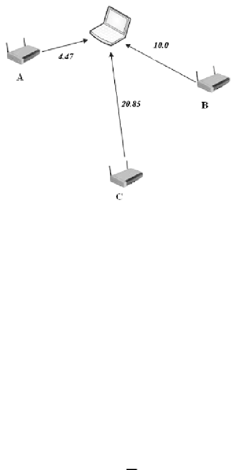
Fig. 2.
Propagation Example.
Each of these distances represents the radius of a circle centered on the
respective access point. There is only one possible location where these three
distance lines can intersect at a single point. This point represents the device's
location.
While a flat surface requires signals from three access points to pinpoint a
location, to locate a point in three dimensional space, such as a multi-floored
building, four access point signals are needed by the propagation model. Geo-
metrically this can be viewed as the intersection of four spheres as opposed to
the three circles described in the plane.
The Wall Attenuation Factor Model.
In order to compensate for the ef-
fects of physical obstructions at a wirelessly networked site Microsoft Researchers
working on the RADAR project [1] modified the Floor Attenuation Factor prop-
agation model [17] in what they call the Wall Attenuation Factor model to
account for obstacles (i.e.: walls) rather than floors.
The Wall Attenuation Factor (WAF) model [1]:
10
n
log
d
d
0
nW
∗
WAF
nW < C
P
(
d
)[
dBm
]=
P
(
d
0
)[
dBm
]
−
−
(2)
C
∗
WAF
nW
≥
C
-
n
is the rate at which the path loss increases with distance
-
P
(
d
0
) represents the signal strength at some distance
d
0
-
d
is the transmitter-receiver separation distance
-
C
is a constant that represents the number of obstructions that are factored
into the model and the threshold above which
nW
makes no difference
-
nW
is the number of obstructions between the transmitter and receiver
-
WAF
is a constant that represents the wall attenuation factor
-
The values
n
and
WAF
are derived empirically based on the building layout
and construction material
Search WWH ::

Custom Search