Civil Engineering Reference
In-Depth Information
where
ξ
0
is an initial value that is dependent on specific material properties and
the magnitude of the applied current,
t
represents time, and
b
is an exponential
term. The
ξ
0
value is similar to the
C
-term in the power law equation, where it
is dependent on the specific material (i.e., its strength, crystal structure, etc.).
Although the EEC does not simply vary in time, the term “time” is related to the
deformation parameters. Equation (
4.7
) can be rewritten in terms of strain, as
shown in Eq. (
4.8
), where
ε
is the material strain and
ε
is the strain rate (i.e., the
deformation speed).
ε
ε
b
ξ = ξ
0
×
(4.8)
4.2.2 Experimental Setup and Procedure
The main experimental objective of this section was to measure the thermal pro-
file during the EAF test and use it to generate an EEC profile. Figure
4.7
displays
the experimental setup used for testing. An Instron Model 1332 hydraulic testing
machine was used to compress the specimens. Machined, hardened, and insulated
dies, made from A2 tool steel, were installed in the Instron machine
(note that
insulation was used such to isolate the electricity from the test machine)
. For ther-
mal measurements, a FLIR A40 M thermal camera, with a temperature capacity
of 550 °C, resolution of 0.1 °C, and sample frequency of 50 Hz was utilized. All
force and position data were gathered using an onboard data acquisition system at
1,500 Hz sampling frequency.
The materials tested were two grades of titanium: Grade 2, which is a single
phase polycrystalline material and Grade 5 (Ti-6Al-4V), a dual-phase alpha-beta
alloy. The initial dimensions of the specimens are summarized in Table
4.1
. A dis-
placement speed of 12.7 mm/min was used for all tests and a constant DC current
of 300 A was utilized for all the EAF tests. Please note that, since the cross-sec-
tional areas between the specimens of the three levels of deformation will be dif-
ferent, the resulting current densities will also be different. Considering the size
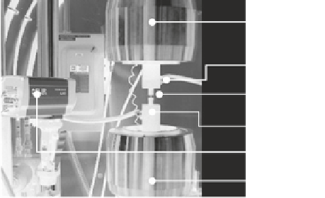
Fig. 4.7
EAF test setup.
The setup consists of the
mechanical testing machine,
dies, and a thermal camera
Upper Grip
Electric Lead
Workpiece
Forging Die
FLIR Camera
Lower Grip