Civil Engineering Reference
In-Depth Information
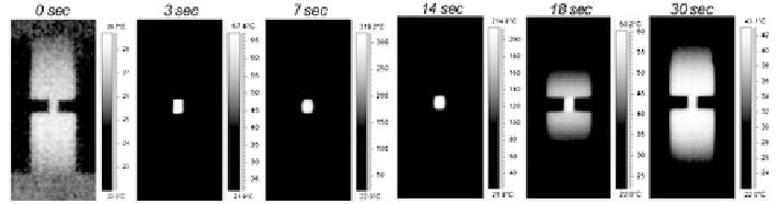
Fig. 4.4
Heating and cooling sequence of a stationary electrical experimental test. Throughout
the beginning of the test, the specimen absorbs the majority of the heat, but during the second
half, a lot of heat is conducted into the dies
contact resistance effect becomes negligible. The die/specimen interfaces will
also have a different temperature distribution, and these boundary conditions
will be taken into consideration when the solution for the model is calculated.
• The voltage in the specimen is assumed constant, and it is determined for the
initial dimensions of the specimen at room temperature. However, the voltage
will vary during the test, since the power supply used is a variable-voltage
source (i.e., constant current). On one hand, the decrease of the ratio of height
over cross-sectional area results in lower resistance, thus lower voltage, while
the increase in temperature will increase the resistivity, thus resistance and
voltage increase. Overall, the present work assumes that these effects cancel
each other.
The temperature rise and its distribution during an electrical test are illustrated
in Fig.
4.4
during a stationary electrical test, where electricity is applied without
plastic deformation. It can be seen that the specimen quickly heats up for about the
first 14 s with almost all the heat going exclusively into the workpiece. Then, the
heat from the specimen conducts into the compression dies for the remaining half
of the stationary electrical test.
When examining only the specimen, the specific temperature profile will also
change throughout the test. More specifically, the temperature of the die/workpiece
contact points at the beginning of the test will be much hotter than the rest of the
specimen (because the actual contact area will be less, leading to a higher overall
electrical power at these points). However, as the part is compressed and the asperi-
ties are crushed, the temperature profile inverts and the middle of the specimen is
the hottest (since the asperities crush and the contact area increases, leading to a
decrease in the electrical power at these points). In addition, the heat generation is
reduced to a point that it cannot keep up with conduction into the dies. The esti-
mated thermal profiles of an EAF test are schematically illustrated in Fig.
4.5
.
For a better understanding of the electroplastic effect, the thermal aspects must
be isolated. When the electric current passes through the metallic workpiece, heat
is generated and the temperature of the part rises. The temperature increase is
determined from the energy balance, illustrated in Fig.
4.6
.