Civil Engineering Reference
In-Depth Information
should be noted that the entire dislocation core does not move all at one time, but
regions of the core advance through the lattice over time. This does not affect the
results presented as they are examining the magnitude between Joule heating and
the electron wind effect.
In addition, the localized Joule heating effect can be quantified as a temperature
rise by
T
=
J
2
ρ
E
ρ
C
T
(3.4)
where
T
is the temperature rise,
J
is the current density,
ρ
E
is the electrical resis-
tivity of the area of interest,
T
is the change in time,
ρ
is the density, and
c
is the
specific heat. Due to the difference in electrical resistivity between the defect-free
lattice and dislocation core, the temperature magnitude is linearly scaled from the
variation in resistivity (i.e., dislocation core is seven times hotter than the defect-
free lattice) as per Eq. (
3.4
). To characterize this effect, a simplified model which
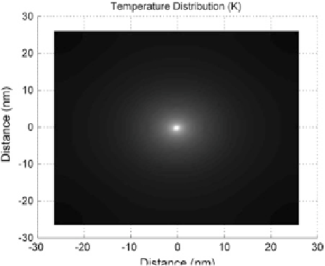
includes transient conductive heat transfer from a 2D nodal mesh is shown in
Fig.
3.2
.
This model was produced to understand the heat generation and dissipation
during Joule heating around a dislocation core. As seen, the dislocation core in the
center generates the greatest heat and is dissipated outward from the core center.
Future use of this model could allow for the inclusion of additional defects (dis-
locations, point defects, and interfacial defects) such that a mean or bulk tempera-
ture could be calculated over a larger area. This bulk temperature from the model
would allow for a comparison to experimental thermal results. Additionally, as
deformation is imposed, newly formed dislocations could be incorporated into the
model with some dislocation distribution to quantify the addition of new disloca-
tions on the heat transfer response.
Fig. 3.2
Snapshot of
transient response of joule
heating as a result of the
greater dislocation core
electrical resistance