Civil Engineering Reference
In-Depth Information
p
Thermal
camera
Press
Power
source
Insulation
Te mperature
measurements
Die
+
_
Workpiece
~
DAQ
System
V
Position and Force
measurements
A
p
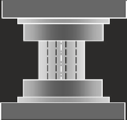
Fig. 2.1
Schematic of an EAF test setup [
1
]. During EAF, electricity is applied to a metal while it is
deformed, thus increasing the overall formability of the metal and producing the electroplastic effect
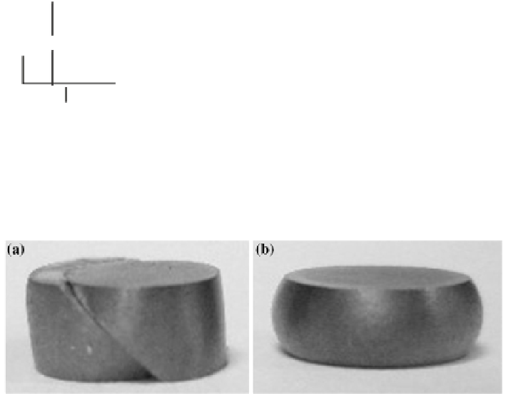
Fig. 2.2
EAF formability improvement (Ti-G5) [
1
]. EAF increases the achievable amount of part
displacement before failure.
a
Conventional forming of a Ti-G5 slug led to almost instantaneous shear
failure,
b
EAF forming of the same material enabled the slug to be deformed to its desired distance
However, like all processing techniques, EAF has some disadvantages and chal-
lenges that exist within the process and its implementation toward industrial use.
First, in order for the electricity to reach the part, there must be some type of electri-
cal applicator in contact with the conductive workpiece at all times. For manufactur-
ing processes where the workpiece is stationary, like forging or stamping, this can
be done rather easily. Conversely, when implementing the EAF technique on man-
ufacturing processes with workpieces of relative motion, like friction welding two
workpieces together, an applicator system which is in continuous contact with the
workpiece while not becoming entangled in the part must first be designed. In addi-
tion, since the workpiece is subjected to electrical flow, all personnel and machine
components should be insulated from the electricity. It must be noted that extreme
caution should always be used when working with electricity. Isolating the electric-
ity, however, can prove to be a challenging task in some cases, since most machin-
ery components are comprised of conductive metals and the common insulating