Civil Engineering Reference
In-Depth Information
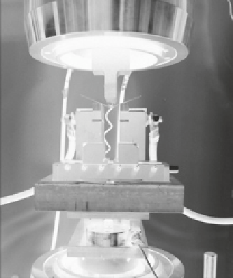
Top Platen
Punch with insulation
Sheet Specimen
Electrical Cable
Adjustable Bending Die
with insulation
Insulation
Load Cell
Bottom Platen
Fig. 11.6
EAB test setup [
1
,
2
]. All key components are listed, and the insulation component are
comprised of fiberglass-reinforced plastics for their compressive strength
There were two possible configurations for placing the insulation and directing
the electrical flow. The chosen configuration was to apply the electricity on one side
of the bending fixture and have it travel through the specimen to the other side of
the fixture. The top punch was completely insulated except for the tip. Another con-
figuration could have been to apply the electricity through the top punch. In this
case, the electricity enters the center of the specimen and then about half of the
electricity flows through one side of the bending fixture and the other half flows
through the other side. This configuration was not optimum in this case because
now the electricity was flowing in parallel and the voltage was reduced by half.
When first testing the bending fixture, some fundamental design flaws were real-
ized in the points of the fixture which contacted the sheet metal specimen and trans-
mitted the electrical current into the specimen. Figure
11.7
a shows the initial design
of these components. Every time an electrical pulse was applied, the sheet specimen
would weld itself to the fixture and this would ultimately increase the bending force
after each electric pulse, until the small weld broke. This can be observed in the force/
displacement plot. Careful evaluation revealed that the large radii on these contact
points caused the line of contact between the fixture and the specimen to constantly
move with bending displacement, and the relative velocity between the dies and the
part is small. Due to the presence of asperities, until the contact is re-established, it is
possible that gaps form, thus allowing for welding to occur. As a solution to this, a sec-
ond design, with a very small radius, was tested. Because the radii on this design were
much smaller, the contact point between the fixture and the specimen did not change
as much. This design, coupled with a thin film of dielectric grease placed on the fixture
contact points, primarily prevented any welding. The result is force/displacement pro-
files as shown in Fig.
11.7
b, where the electricity lowers the bending force.