Civil Engineering Reference
In-Depth Information
demonstration also leads to the opportunity for present forming machine architec-
tures/designs to be modified with the goal of becoming more flexible, which is
highly desirable in industry.
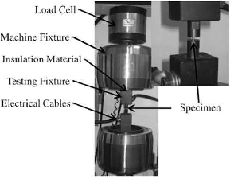
7.3 Constant Current Density Forming
CCD forming has been performed for uniaxial compression upsetting (Fig.
7.15
)
for both 304 Stainless Steel and Grade 5 titanium (Ti-6Al-4V). The internal block
diagram for the overall control of the current scheme is shown in Fig.
7.16
.
In the block diagram, the initial state of the force and load is set to use as a
reference point. Then, depending on the desired process (NCCD or CCD), the
controller calculates the feed voltage that gets supplied to the current source. The
current source reads the feed voltage and outputs a corresponding electrical cur-
rent to the forming process. This process is repeated until the desired amount of
material strain is reached. For the NCCD tests, the supplied current is constant
and the shape change makes the current density decrease with time (compression
tests). For the CCD tests, the supplied current is increased with time to maintain a
CCD irrespective of specimen shape change.
The variation in the material flow stress by taking into consideration compo-
nent shape change during the forming process is shown in Figs.
7.17
and
7.18
for
304 Stainless Steel and Grade 5 titanium, respectively. As seen, by modulating
the current during the test, the material flow response is altered as compared with
using only a nominal current value. As a note, for compression forming, the cur-
rent is applied continuously during the entire forming process. These results pro-
vide a better representation of the actual material stress due to an applied current
as specimen shape is not a factor.
Fig. 7.15
Constant current
density forming setup. The
specimen is pressed between
two platens