Civil Engineering Reference
In-Depth Information
6.1.1 Model Development
In the following two sections, the development of the thermal stationary model for
process variable identification and the thermal deformation model for verification
and understanding of the electroplastic effect are presented.
6.1.1.1 Stationary Model
The stationary model was created for a stationary test (i.e., no deformation) of
an ASTM tensile specimen subjected to an applied direct electrical current. This
model is used for process variable identification and overall modeling methodol-
ogy and construction validation. The key process variables to be identified were
the heat transfer convection coefficient, initial component and clamping die tem-
peratures, the power supply efficiency and its associated losses, and effective
clamping die conduction length in the clamped region. As this model is the basis
for the subsequent thermal deformation model, it is described in detail.
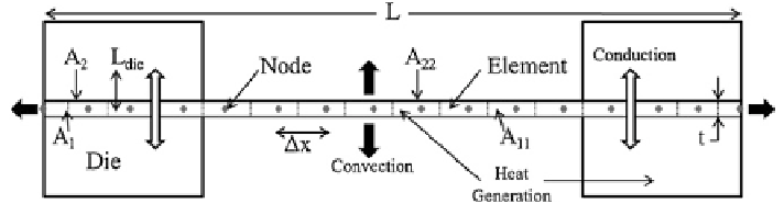
The constructed 1D transient finite-difference thermal model is of a standard
12.5-mm-wide ASTM tensile specimen [
1
] that is to be used for the uniaxial test-
ing of EAF, and the model contains equally spaced nodes along the length of the
specimen (Fig.
6.1
).
The model accounts for:
1. Heat conduction throughout the specimen
2. Heat conduction to the dies in the clamping region
3. Heat convection to the environment in the testing region
4. Joule heating of the specimen and dies when the direct electrical current is applied
(corresponds to varying wave shapes, magnitudes of current, and duty cycles)
5. Temperature-dependent material properties of the sheet material (density, elec-
trical resistivity, thermal conductivity, and heat capacity) [
2
]
The model is based on the following assumptions:
1. The temperatures across the width and thickness of the specimen are uniform,
and the temperature only varies along the length of the specimen (i.e., it is
Fig. 6.1
Stationary thermal model schematic