Environmental Engineering Reference
In-Depth Information
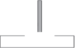
figure 4.33 Globe valve.
presses against the valve seat to close the valve. The disk is the part of
the globe valve that controls flow. The disk is attached to the valve stem.
As shown in Figure 4.33, fluid flow through a globe valve is at right angles
to the direction of flow in the conduits.
Globe valves seat very tightly and can be
adjusted with fewer turns of the wheel
than gate valves; thus, they are preferred
for applications that call for frequent
opening and closing. On the other hand,
globe valves create high head loss when
fully open; thus, they are not suited in
systems where head loss is critical.
Key Point:
The globe valve should never be
jammed in the open position. After a valve is fully
opened, the hand wheel should be turned toward
the closed position approximately one-half turn.
Unless this is done, the valve is likely to seize in
the open position, making it difficult, if not impos-
sible, to close the valve. Another reason for not
leaving globe valves in the fully open position is
that it is sometimes difficult to determine if the
valve is open or closed (
Valves
, 1998).
4.13.2.4 Needle Valves
Although similar in design and operation to the globe valve (a varia-
tion of globe valves), the needle
valve has closing element in the shape
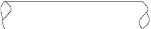
of a long tapered point, which is at the end of the valve stem. Figure 4.34
shows a cross-sectional view of a needle valve. As you can see in the fig-
ure, the long taper of the valve closing element permits a much smaller
seating surface area than that of the globe valve; accordingly, the needle
valve is more suitable as a throttle valve. In fact, needle valves are used
for very accurate throttling.
4.13.2.5 Butterfly Valves
Figure 4.35 shows a cross-sectional view of a butterfly valve. The
valve itself consists of a body in which a disk (“butterfly”) rotates on a
shaft to open or close the valve. Butterfly valves may be flanged or wafer
design, the latter intended for fitting directly between pipeline flanges.
In the full open position, the disk is parallel to the axis of the pipe and
the flow of fluid. In the closed position, the disk seals against a rubber
Flow
Flow
figure 4.34 Common needle valve.