Environmental Engineering Reference
In-Depth Information
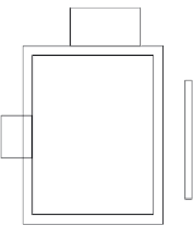
Discharge
roat
Impeller
Inlet
Shaft
Packing
Casing chamber
figure 3.15 Schematic of a recessed impeller or vortex pump.
3.3.9.2.3 disadvantages
Because of the reduced direct contact between the liquid and the
impeller, the energy transfer is less efficient. This results in somewhat
higher power costs and limits the application of this pump to low to
moderate capacities. Objects that might have clogged a conventional
type of centrifugal pump are able to pass through the pump. Although
this is very beneficial in reducing pump maintenance requirements, it
has, in some situations, allowed material to be passed into a less acces-
sible location where it becomes an obstruction. To be effective, the pip-
ing and valving must be designed to pass objects of a size equal to that
which the pump will discharge.
3.3.9.3 Turbine Pumps
The turbine pump consists of a motor, drive shaft, discharge pipe of
varying lengths, and one or more impeller-bowl assemblies (see Figure
3.16). It is normally a vertical assembly, where water enters at the bot-
tom, passes axially through the impeller-bowl assembly where the
energy transfer occurs, then moves upward through additional impel-
ler-bowl assemblies to the discharge pipe. The length of this discharge
pipe will vary with the distance from the wet well to the desired point of
discharge.
3.3.9.3.1 application
Due to the construction of the turbine pump, the major applications
have traditionally been for pumping relatively clean water. The line shaft
turbine pump has been used extensively for pumping drinking water,
especially in those situations where water is withdrawn from deep wells.
The main wastewater plant application has been pumping plant effluent
back into the plant for use as service water.