Civil Engineering Reference
In-Depth Information
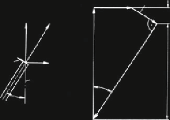
Fig. 2.1 Forces on the wire
of a strand
U
i
Q
i
Q
i
sin
ʱ
i
S
i
F
i
Q
i
S
i
U
i
F
i
F
i
cos
ʱ
i
strand-
axis
ʱ
i
ʱ
i
outer forces on the single wire in the wire layer i of a strand. The division of the
strand tensile force and torque in the wire forces S
i
and U
i
will be described later
on. For the present, S
i
and U
i
will be presupposed as known.
Both outer forces S
i
and U
i
on a wire must be in balance with the inner forces,
the wire tensile force F
i
and the wire shear force Q
i
. The forces on a wire of a wire
layer i are shown in Fig.
2.1
. From these, using r
i
for the lay angle, both of the
following equations can be derived
F
i
¼
S
i
Q
i
sin a
i
cos a
i
ð
2
:
1
Þ
and
U
i
¼ F
i
sin a
i
Q
i
cos a
i
:
ð
2
:
2
Þ
The shear force Q
i
of a wire of layer i is caused by the bending and torsion of
this wire, of course geometrically limited by the rope extension. As was first
presented by Berg (
1907
), the shear force of a wire in layer i is
Q
i
¼
sin a
i
r
i
:
M
b
;
i
cos a
i
M
tor
;
i
sin a
i
ð
2
:
3
Þ
with the wire winding radius r
W,i
= r
i
, the bending moment M
b,i
around the bi-
normal and the torque M
tor,i
around the wire axis. With this the tensile force in a
wire of the wire layer i is
sin
2
a
i
r
i
cos a
i
:
S
i
cos a
i
F
i
¼
M
b
;
i
cos a
i
M
tor
;
i
sin a
i
ð
2
:
4
Þ
According to Berg (
1907
), the portion of the strand torsion moment caused by a
wire of the wire layer i is


Search WWH ::

Custom Search