Civil Engineering Reference
In-Depth Information
1.5
D/d = 25
D/d = 63
1.0
0.8
D/d = 12.5
0.6
0.5
0.4
0.3
parallel lay
FC and WRC
8x19 sZ and zZ
cross lay 6x19 FC
Seale 8x19 WRC
WS 6x36 FC sZ
D/d = 12.5
D/d = 25
D/d = 63
Müller
Jehmlich
Jehmlich
0.2
D/d = 25
0.15
4
5
6
2
35
23 5 10
23 5 10
23
number of bending cycles N
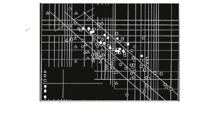
Fig. 3.57 Ratio of breaking number of reverse and simple bending cycles N
rev
/N
sim
, Feyrer and
Jahne (
1991a
)
Jehmlich. The ratio of the numbers of reverse and simple bending cycles N
rev
/N
sim
increases with the decreasing number of simple bending cycles and with the
increasing diameter ratio D/d.
For very small numbers of simple bending cycles, the ratio N
rev
/N
sim
is partly
even greater than 1. That means that the number of reverse bending cycles is
greater than those of simple bending cycles. This surprising result is caused mainly
by the standard definition of a bending cycle. According to these standard defi-
nitions, the reverse bending cycle (bent—straight—reverse bent) is in reality a
half-stress cycle. It is only after two reverse bending cycles that the wire rope will
have returned to the same condition as at the beginning. In contrast, the simple
bending cycle (bent—straight—bent) is a whole stress cycle. Furthermore, the
fluctuating pressure works—with the same numbers of cycles in both cases—on
one side of the rope in simple bending cycles and half and half on two rope sides in
reverse bending cycles.
By definition, the reverse bending cycle means that the axes of the two sheaves
involved are parallel. Research into bending fatigue tests with wire ropes running
over several sheaves with axes which are not parallel has not been carried out up to
now.
3.2.5 Fluctuating Tension and Bending
Two types of fluctuating tension and bending exist: independent and combined. In
Fig.
3.58
, the course of the longitudinal wire stress with independent tension and


Search WWH ::

Custom Search