Civil Engineering Reference
In-Depth Information
FC 8
×
19
5,0
WRC 8
19
×
_
_
FC 6
×
36
N
N
_
_
(
ʽ
=const )=const
WRC 6
×
36
D/d = 25
N
N
1770
3,0
1770
S/d
2
=117N/mm
2
2,0
1,0
0,5
0,3
0,2
1280
1770
1370
1770
1570
1770
1770
1770
1960
1770
2160
1770
2350
1770
ratio of nominal strength R
0
/1770
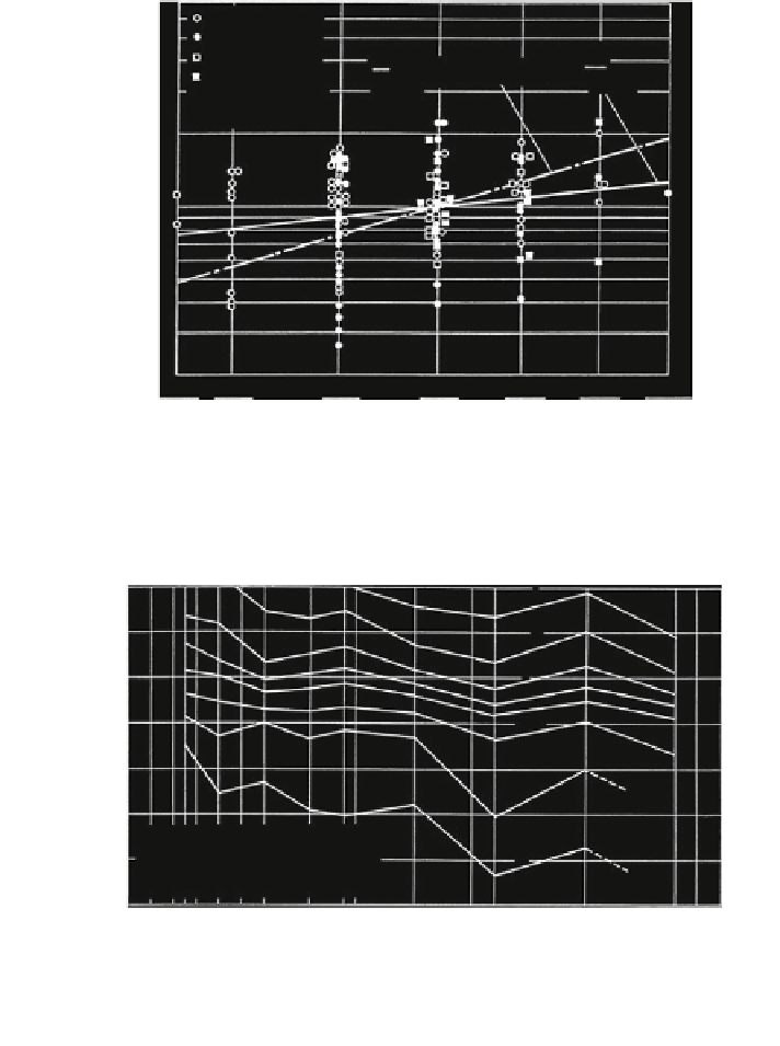
Fig. 3.37 Influence of the nominal tensile strength on the breaking number of bending cycles
N for D/d = 25 and S/d
2
= 117 N/mm
2
10
7
10
6
10
5
˃
z
=30
˃
z
=40
10
4
˃
z
=60
10
3
10
2
D/d = 25
r /d = 0,53 d
R0 = 1570 - 1960 N/mm
2
10
1
02
46 8 0 ,515 16
20
mm
24 25
rope diameter d
Fig. 3.38 Breaking numbers of bending cycles of cross lay ropes 6 9 19 - FNC - sZ of
different nominal rope diameters, Müller, H.: Drahtseile im Kranbau. VDI-Bericht Nr. 98 und dhf
12(11), S714-716 (
1966
)
The endurance factor expresses the ratio between the breaking or discarding
number of bending cycles of a rope pieces (with rope diameter d and bending length
l = 60d) and that of the reference rope bending length (with rope diameter
d
E
= 16 mm and l
E
= 60d
E
). With the exception of the rope diameter, all other data of
influence are constant. The endurance factor for one pair of bending cycle numbers is
Search WWH ::

Custom Search