Civil Engineering Reference
In-Depth Information
25
Grad
S/d
2
= 68.3 N/mm
2
Müller (1966)
W
−
S. + FE d=11. 9 mm
W
−
S. + FE d=16. 3 mm
W
20
W
−
S. + FE d=23. 7 mm 8 Li .
−
S. + FE d=24. 1 mm
W
−
S. + FE d=26. 1 mm
W
−
S. + FE d=26. 6 mm
15
W
−
S. + FE d=27. 8 mm
W
−
S. + SE d=24. 1 mm
W
−
S. + SE d=26. 6 mm
W
−
S. + SE d=27. 4 mm
W
−
S. + SE d=27. 7 mm
S. + SE d=24. 2 mm
10
S/d
2
= 30.0 N/mm
2
68.3 N/mm
2
300.0 N/mm
2
9
8
ʔˑ
1
ʔˑ
2
7
6
5
10
20
50
100
diameter ratio D/d
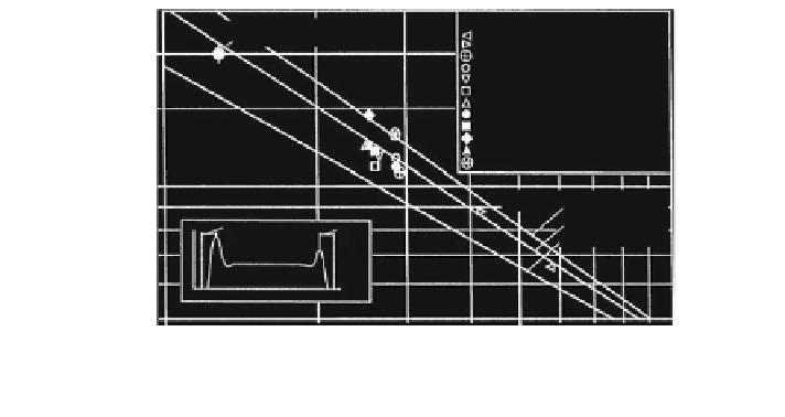
Fig. 3.21
Winding angle difference D
#
, Häberle (
1995
)
tensile force S/d
2
= 62.5 N/mm
2
, is drawn in Häberle's Fig.
3.21
and conforms
to a great extent with the angle difference D
#
for the specific tensile force
S/d
2
= 68.3 N/mm
2
. Admittedly, however, the construction of the wire ropes used
in Figs.
3.21
and
3.53
is not identical.
Example 3.3
Rope line pressure
Data:
Warrington-Seale rope 6 9 36 sZ
Rope diameter d = 16 mm
Ratio r/d
m
= 0.54
Sheave diameter D = 400 mm
Rope tensile force S = 30 kN
Results:
Global line pressure, (
3.27
): q
0
¼
2
30
;
000
400
¼ 150 N
=
mm
:
Maximum line pressure, (
3.28
)
lg
q
max
q
0
¼
1
:
887
0
:
607
lg 117
0
:
939
lg 25
þ
0
:
316
lg 117
lg 25
¼
0
:
2324
q
max
q
0
¼
1
:
71
q
max
¼ 1
:
71
150 ¼ 256 N
=
mm
:
Winding angle difference, (
3.29
)
lg D
#
¼ 2
:
870
0
:
383
lg 117
1
:
073
lg 25
þ
0
:
171
lg 117
lg 25 ¼ 1
:
0722
D
#
¼ 11
:
8
:
Search WWH ::

Custom Search