Civil Engineering Reference
In-Depth Information
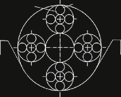
Fig. 3.4 Bending stresses in
the wires of a lang lay rope
between straight and bent,
Schiffner (
1986
)
bending stress
constant ratio of
winding angle
ˑ
/
˕
bending stress
constant
lay angle
195
241
402
402
471
471
351
428
410
349
410
349
551
588
588
551
491
499
499
491
419
ʱ
= 18
ʲ
= 18
r
w
= 2.0 mm
r
s
= 5.5 mm
ʴ
419
354
354
363
444
420
420
497
497
= 1.0 mm
D = 400 mm
199
255
stresses in N/mm
2
Fig. 3.5 Torsion stresses in
the wires of an ordinary lay
rope between straight and
bent, Schiffner (
1986
)
torsion stress
constant ratio of
torsion stress
constant
lay angle
winding angle
ˑ
/
˕
3
49
4
5
4
5
−
35
−
45
57
51
5
57
−
1
−
1
0
0
0
0
−
58
−
58
−
ʱ
= 18
ʲ
= 18
r
w
= 2.0 mm
r
s
= 5.5 mm
ʴ
−
52
52
3
47
5
−
5
−
−
6
−
6
= 1.0 mm
D = 400 mm
−
40
−
53
stresses in N/mm
2
The highest fluctuating bending stress (between straight and bent) occurs in
wires inside the rope. It is here, therefore, that the first wire breaks have to be
expected if all the other wire stresses are small. This is the case for wire ropes
running over sheaves with soft grooves (small elasticity module) which keep the
pressure on the wires down. With grooves made of steel, cast iron or other hard
material (high elasticity module), the pressure on the wires together with the
bending stress can be great enough to produce wire breaks, first of all in the contact
zone with the groove. This is normally the case for ordinary lay ropes but mostly
not for lang lay ropes which only have a very low bending stress at this point. This
is the reason why—except for special cases—visible wire breaks are only reliable
as a wire rope discarding criterion for ordinary lay wire ropes running over sheaves
with grooves made of steel or cast iron.


Search WWH ::

Custom Search