Civil Engineering Reference
In-Depth Information
Table 1.3 Strength of drawn wires out of corrosion resistant steel (excerpt of prEN 10 088-
3:2001, Table
1.8
)
Steel name
Strength range (N/mm
2
)
Steel number
X10CrNi18-8
1.4310
600-800
X5CrNiMo17-12-2
1.4401
900-1,100
X3CrNiMo17-13-3
1.4436
1,000-1,250
X1CrNiMoCuN20-18-7
1.4547
1,400-1,700
X1CrNi25-21
1.4335
1,600-1,900
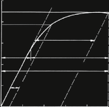
2500
R
m
=2224 N/mm
2
N/mm
2
R
p0.2
=1940 N/mm
2
2000
residual extension
ʵ
r
elastic
extension
ʵ
e
1500
plastic
extension
ʵ
pl
1000
total extension
ʵ
t
ʵ
=0.2 %
500
0
0
0.2
0.5
1.0
extension
1.5
2.5
2.0 %
ʵ
Fig. 1.3
Stress extension diagram of a straightened wire, d = 1.06 mm
However, the yield strength is defined for a small residual extension. Here, the
most frequently used extension is e = 0.2 % and the stress at this point is the yield
strength R
p0.2
. The elasticity module can be evaluated with a special tensile test.
If only the tensile strength R
m
has to be evaluated, it can be done without
straightening the wire. However, if the different extensions and the yield strength
have to be evaluated too, the wire has to be straightened prior to testing. The
measurement starts at a stress of about 10 % of the tensile strength R
m
. Under this
stress, the height of the wire bow at a distance measured of 100 mm should be
smaller than 0.5 mm.
A typical stress-extension diagram of a straightened wire is shown in Fig.
1.3
.
It is possible to take the tensile strength R
m
, the total extension e
t
and the residual
extension e
r
directly from this figure. To determine the elasticity module E and the
yield strength R
p0.2
, the following method has to be used. After a certain yielding,


Search WWH ::

Custom Search