Civil Engineering Reference
In-Depth Information
u
90
¼ arcsin
8
;
000
16
ð
0
:
085
þ
1
:
282
0
:
012
Þ
¼ arcsin 0
:
4283
200
150
u
90
¼ 25
:
4
According Eq. (
2.81b
) the total rotary angle that the bottom sheave not exceed
is
u
rtot
¼ arcsin 2
:
06
0
:
4283 ¼ arcsin 0
:
8823
u
tot
¼ 61
:
9
:
An overlapping of the bearing rope traces is not to fear.
2.4.4 Rope Twist Caused by the Height-Stress
2.4.4.1 Wire Rope Supported Non-rotated at Both Ends
Because of the rope weight the tensile force in a suspending rope has on the upper
end a bigger tensile force than on the lower end. The rope stress increasing with
the height of the suspending rope is called height-stress. Because the rope torque
along the rope length must be constant, the wire rope supported non-rotated on the
upper and the lower end will twist between the both ends. The rotary angle of a
vertical hanging wire rope is demonstrated in Fig.
2.29
. The rope turns on in the
upper field and off in the lower field.
Engel (
1957
) and little later Hermes and Bruuens (
1957
) derived at first the rotary
angle caused by the height-stress, see also Gibson (
1980
). Engel (
1959
) calculated
the twist angle for haul and traction ropes of rope ways. Rebel (
1997
) calculated
with his own equation the rotation of triangular strand ropes in deep shafts.
Malinovsky and Tarnavskaya (
2006
) derived their calculation method reminding
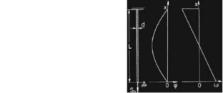
Fig. 2.29 Rotary angle u
and twist angle x of a vertical
hanging wire rope supported
on both ends non-rotated
Search WWH ::

Custom Search