Biology Reference
In-Depth Information
(a)
(b)
lower density first
higher density first
back
reservoir
mixing
chamber
back
reservoir
mixing
chamber
pump
pump
tube
tube
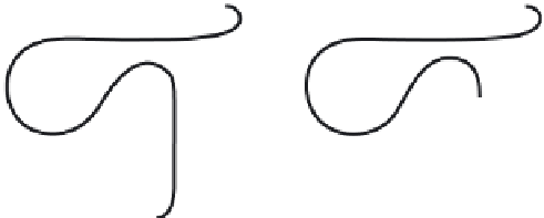
FIGURE 12.9
Formation of continuous density gradients using a density gradient maker. The device consists
of two chambers, one of which contains a heavy (dense
e
clear) solution. The densities of the two solutions will eventually define the final solution density at the bottom
and top of a centrifuge tube. The chamber on the right (the mixing chamber) has a mixer and an outlet where the
mixed solution is pumped into the centrifuge tube. The chamber on the left holds a reservoir that is slowly
added to the mixing chamber, but has no direct outlet to the centrifuge tube. Two types of density gradient
systems are depicted, Lower Density First (Panel a) and Higher Density First (Panel b). Lower Density First: the
lower density solution, initially in the mixing chamber, is first added to the bottom of the centrifuge tube. As the
process continues the denser solution, initially in the back reservoir, is slowly added to the mixing chamber,
increasing its density. Therefore the initial low density solution is continuously replaced from the tube bottom
by a more dense solution, creating the gradient. Higher Density First: the solutions are reversed, with the
denser solution in the mixing chamber. Therefore the first solution added to the tube is the most dense. In
contrast to the low density first method, the solution is added from the top of the centrifuge tube. The gradient
is made by adding less dense solutions from the top.
e
black balls) solution and the other a light (less dense
ways of making a continuous gradient using a gradient maker, the Lower Density First
method (
Figure 12.9
a) and Higher Density First method (
Figure 12.9
b). Both methods are
based on mixing two solutions of different density before adding them to the centrifuge
tube. Details of the procedures are given in the legend for
Figure 12.9
.Gradientscanbe
shallow (the two initial solutions have similar densities) or steep (the two initial solutions
have very different densities). Shallow gradients are used to separate particles of similar
physical properties. While separation of large, cell homogenate components (e.g. nuclei,
mitochondria, chloroplasts etc) is relatively easy and can often be done with just differential
centrifugation, separation of microsomes (small cell vesicles) is difficult. All microsomes
have similar physical properties including size, shape, and density but may be separated
using shallow density gradient centrifugation methodologies.
Some solutes have the ability to self-generate a density gradient during centrifugation.
Examples include cesium chloride (CsCl), Percoll
. The major
application for CsCl is in separating very dense molecules like nucleic acids. The density
of DNA is about 1.7 g/ml and RNA about 2 g/ml while membrane vesicles fall between
1.1
, Ficoll
and OptiPrep
1.3 g/ml, the range covered by Percoll, Ficoll and OptiPrep.
e