Database Reference
In-Depth Information
equally weighted partitions over
p processors so that the total weight of the edges
crossing between partitions is minimized (see Section 1.4.4). Unfortunately, by
carefully inspecting such a strategy, we realize a serious shortcoming that directly
impacts communication. To exemplify, Figure 1.11 in Section 1.4.4 shows that the
minimum cut resulted from the edge cut metric overlooks the fact that some edges
may represent the same information flow. In particular,
v
2
at
P
1
in the figure sends
the same message twice to
P
2
(specifically to
v
4
and
v
5
at
P
2
), while it suffices to
communicate the message only once, since
v
4
and
v
5
will exist on the same machine.
Likewise,
v
4
and
v
7
can communicate messages to
P
1
only once but they do it twice.
Therefore, the standard edge cut metric causes an over-count of the true volume of
communication and consequently incurs superfluous network traffic. As an outcome,
interconnection bandwidth can be potentially stressed and performance degraded.
Even if the total communication volume (or the number of messages) is minimized
more effectively, load imbalance can render the bottleneck. In particular, it might
happen that while the communication volume is minimized, some machines receive
heavier partitions (i.e., partitions with more vertices) than others. An ideal, yet a
challenging approach, is to minimize communication overheads while circumvent-
ing computation skew among machines. To summarize, this technique strives for
effective partitioning of work across machines so as highly communicating entities
are co-located together
.
The second technique is
effective mapping of partitions
. Specifically, the map-
ping strategy of partitions to machines, whether graph or data partitions, should be
done in a way that is totally aware of the underlying network topology. This dictates
the number of switches that a message will hit before it reaches its destination. As
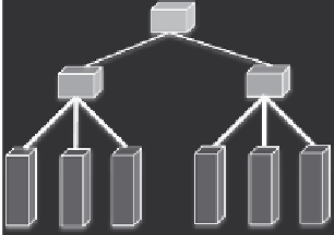
a specific example, Figure 1.14 demonstrates the same graph shown previously in
Figure 1.11 and a simplified cluster with a tree-style network and six machines. The
cluster network consists of two rack switches (RSs), each connecting three machines,
and a core switch (CS) connecting the two RSs. A salient point is that the bandwidth
P
1
CS
v
1
v
3
RS
RS
v
2
P
3
P
2
v
4
v
8
v
7
M
1
M
2
M
3
M
4
M
5
M
6
v
5
v
6
P
3
is mapped to
M
3
FIGURE 1.14
Effective mapping of graph partitions to cluster machines. A mapping of
P
1
to the other rack while
P
2
and
P
3
remain on the same rack causes more network traffic and
potentially degraded performance.


Search WWH ::

Custom Search