Biomedical Engineering Reference
In-Depth Information
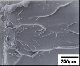
drawing direction. It is thus thought that the ductile deformation due to elongation of the
oriented molecules and the transverse crack formation are primary mechanisms of
toughening in draw-processed PLA. On the other hand, the fracture surface of the parallel
were much smoother than that of the original, corresponding to the lower
J
in
value.
J
in
is
contributed by energy dissipation through not only creation of fracture surface but also
development of process zone. Poralized micrographs of notch-tip regions of the original and
the perpendicular are shown in Fig.7. In the original, multiple crazes forming a fan shape
were observed. They were initiated from the initial notch-tip and propagated almost
perpendicularly to the tensile direction. For the perpendicular with draw ratio 2.5, crazes
were much denser and the width of the damage region was much wider than the original.
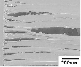
Transverse cracks generated in the drawing direction are observed, and these obviously
correspond to the crevices observed on the fracture surfaces as shown in Fig.6(b). Larger
damage region consisting of crazes and transverse cracks generated in crack-tip region
indicates larger energy dissipation under crack initiation and propagation processes, and
therefore, greater
J
in
.
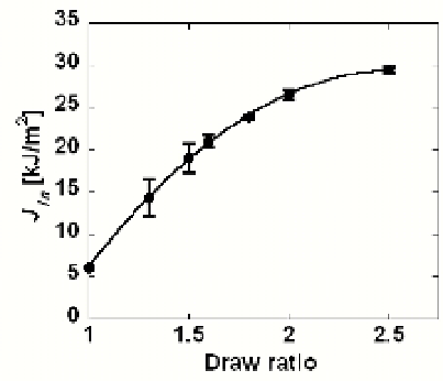
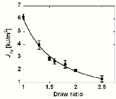
(a)Perpendicular direction (b) Parallel direction
Fig. 5. Dependence of draw ratio on the critical
J
-integral at crack initation.
In summary, it was shown that the crystallization behavior greatly affects the fracture
behavior of PLA. Microstructure of PLA can easily be changed through annealing process
by changing temperature and heating time. The static fracture energy tends to decrease as
crystallinity increases, while the impact fracture energy increases.
(a)Original (b)Drawed, perpendicular (c)Drawed, parallel
Fig. 6. FE-SEM micrographs of fracture surfaces (draw ratio=2.5).