Information Technology Reference
In-Depth Information
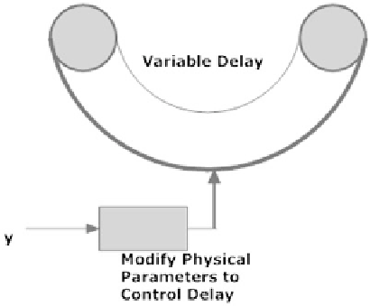
Fig. 4.10
Overview
for delay control
Controlled Toggling
Controlled toggles are most convenient if they have a single input signal to trigger
toggling. There are two ways to cause a multivibrator to toggle, as verified by
simulation in the topic's appendix. The first is termed Excitory/inhibitory Stimula-
tion, the second is termed AND/XOR Triggering.
Excitory/Inhibitory Stimulation for Toggling
This method is perhaps the simplest in that a minimum of neural logic is required.
The plan is to excite multivibration at one point in a loop and simultaneously to
inhibit pulse propagation at a different (well chosen) point in the loop. Figure
4.11
illustrates the plan.
A Single Pulse is used to activate both synapses S11 and S12. Synapse S11 is a
fast excitory synapse that triggers multivibration. S12 is a fast inhibitory synapse
modeled with negative charge injection, with insignificant effect prior to
multivibration, because there is no positive pulse in the vicinity of x3. To stop
multivibration another Single pulse to toggle is applied to both synapses as in the
figure. Multivibration stops because charge is drained from segments near S12,
upsetting the balance necessary for pulse propagation. The time at which a Single
pulse to toggle is applied apparently is not very important according to experimen-
tation with simulations.
AND/XOR Toggling
This method of toggling requires a Single pulse to toggle to be applied at the correct
time. Figure
4.12
shows the circuit. If there is no multivibration, a logic gate detects
Search WWH ::

Custom Search