Information Technology Reference
In-Depth Information
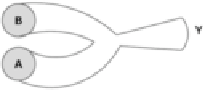
Fig. 3.16
Special junction
for a dendritic XOR gate
In the above model, this behavior depends of the fact that two colliding neural pulses
generally annihilate each other, in which case nothing is transmitted. This is found to
occur if the average capacitance at a junction is reduced slightly.
Physically a slight reduction of capacitance may be accomplished by partial
myelination or by a judicious sprinkling of inhibitory neurotransmitters, although
this would also reduce charging currents. Charging currents could be compensated
by the local structure of the membrane, that is, it could be slightly thinner to
increase charge penetration or the local ionic concentrations surrounding it could
be locally increased very slightly. Capacitance can also be reduced slightly by a
local reduction in diameter as pictured in Fig.
3.16
.
The result is that one pulse will penetrate, but two pulses will not. When two
pulses arrive simultaneously, they collide; colliding pulses annihilate, as clearly
demonstrated by simulations. Thus
Y
¼
A
B
:
(3.6)
It must be emphasized that in order for the above XOR gate to prevent the passage
of two pulses, the pulses must arrive at about the same time. The need for pulse
timing is reduced in enabled logic explained later.
XOR NOT Gate
The XOR function is such that it can be modified to be a NOT gate. This is because
of its theoretical equation:
AB
0
þ
A
0
B
Y
¼
:
(3.7)
1), then B
0
or NOT (B) is false (
If B is made true (
¼
¼
0), and so by algebraic
reduction:
A
0
:
Y
¼
(3.8)
Using neural pulses, the XOR will function as an inverter only under certain
conditions. When pulses are applied to one input, concurrent auxiliary pulses may
applied simultaneously to the other input to make the output zero. But if at any time
only auxiliary pulses are applied to one input and not the other, the output will be
true, with pulses emitted. Pulse coordination is less important using enabled logic
presented later.
Search WWH ::

Custom Search