Information Technology Reference
In-Depth Information
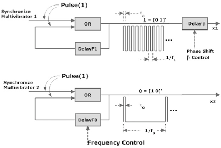
Fig. 10.1
Multivibrators representing true (top) and false (bottom)
The Phase of the 1
Figure
10.1
, top part, suggests an extra multivibrator that is dedicated to
representing phase at frequency f
1
, the 1 state. The phase of the 1 at frequency f
1
is adjusted via Delay
0. So this phase is
also relative to the first pulse of other multivibrators, whose phase shift is zero.
Multivibrator waveforms in this chapter are assumed to be harmonically related in
an attempt to increase the tractability of the analysis. For example, if the low
frequency is 1 Hz, then frequency can step up to its maximum, perhaps 400 in
1 Hz steps. Multivibrators are synchronized by triggering them at the same instant.
Note that the waveform for f
1
in the figure is shown as being 50 % duty cycle,
mainly because 50 % is easy to illustrate. It could happen that duty cycle for the f
1
waveform differs. This is not important below because the only purpose of the f
1
waveform is to register phase.
To simulate a qubit more accurately, the 0 and the 1 must be combined, or held in
superposition. If the media were linear, signals might simply be added producing
two tones at once, as is common mechanically. Unfortunately, neurons are far from
linear, so linear combinations will not work. But two signals may be combined
logically, for instance, in an AND gate as in Fig.
10.2
, although other logical
combinations may also serve. Note that x
1
, x
2
are waveforms from the above figure.
Assuming about equal probabilities for false and true, a composite waveform
(not drawn to scale) is portrayed in Fig.
10.3
. This waveform results by increasing
β
in the figure, and is relative to Delay
β ¼
Search WWH ::

Custom Search