Information Technology Reference
In-Depth Information
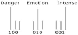
Fig. 6.3
Attribute encoding
the delay chain in Fig.
6.2
for a given group of returns. The single pulse ripples
through the chain, sequentially activating the individual load signals.
Encoder
Once an image is in a register, binary weighting is expected. For instance, assuming
precision N
1
¼
3, a “danger” attribute could translate to 100 as portrayed in
Fig.
6.3
. Other important attributes are translated similarly.
These codes could be intrinsic to attributes in memory. Alternately, they might
be automatically generated by virtue of the location of an attribute, since location is
assumed to define what an attribute means. Not all attributes need weights. Those
whose weights are low are set to zero.
Toggle Registers for Computing Priority
Toggle registers are controlled by codes from long-term memory. The codes
contain fields labeled fm and to. These will be applied to toggle circuits with
connections as in Fig.
6.4
. The circuits are arranged so that if all of the toggle
elements are true in a given fm, the conductor bus will be at rest. But if any one of
the toggle elements is false, the bus is made true. The bus, in this implementation, is
a single interneuron. This method is inspired by a hardware design (Burger patent
number 7,242,599, July 10, 2007).
When the bus is at rest, the toggles in a given to field are flipped, true to false, or
false to true. For example, say the output of
T2
is true. If a fm signal is directed to
T2
, then a false is held to the bus by gate U4. So the bus is at rest. If a to signal is
directed to
T1
, the bus false is inverted to true at the input of gate U1, the output of
which directs
T1
to toggle.
As another example, say a source fm addresses
T1
and
T2
; the complement of
the output
T1
and the complement of the output
T2
are held to the bus. If both the
output
T1
and the output
T2
are true, a false appears on the bus. In other words, if
the AND of the outputs
T1
and
T2
is true, a false is held to the bus; this means the
bus is at rest. So those toggles with a to-signal will flip states.
But if one of or both
T1
and
T2
contain a false at the output, pulses will appear
on the bus. If there are pulses on the bus, the destination toggles identified by the to
will not toggle. Multiple fm signals control multiple to toggles.
Search WWH ::

Custom Search