Information Technology Reference
In-Depth Information
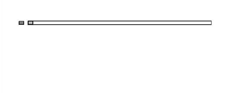
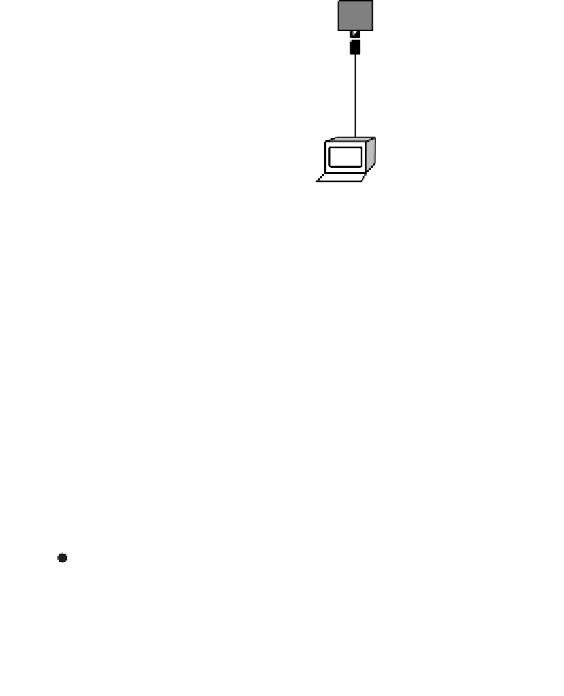
2.5-m Minimum
To other transceivers
N-Connector
Trunk cable
Transceiver (MAU)
500-m Max. length,
max. 100 transceiver
nodes per segment
50-ohm
Terminator
(each end)
DB-15 connector
AUI cable
(50 m max.)
FIGURE B.1
A typical thicknet 10Base5 installation showing distance limitations: 500-m segment, 2.5-m
tap-to-tap, 50-m AUI.
ing resistors minimize reflections of the Mbps signal that would otherwise occur.
Removing a terminator or cutting a backbone cable will cause the network to fail,
as the reflections are inverted and cause a failure in the carrier sense and collision
detection mechanism. Transceivers may generally be connected to a live network
cable, although there is always a possibility that the cable shield and center conduc-
tor may short briefly during the process. Such a short will temporarily disable the
network, but should be cleared quickly when the tap is installed. Some network
managers schedule transceiver installations only during scheduled downtime.
Pin
Function-IEEE 802.3
Ethernet V2.0
1
Control-in shield
Shield
Ethernet
AUI
interface
2
Control-in A
Collision pres.
3
Data-out A
Transmit
4
Data-in shield
-
1
5
Data-in A
Receive
6
Voltage common
Power retn.
7
Control-out A
-
8
Control-out shield
-
15
Transceiver connector
male DB-15 style
9
Control-in B
Collision pres.
10
Data-out B
Transmit
11
Data-out shield
-
12
Data-in B
Receive
13
Voltage
Power
14
Voltage shield
-
15
Control-out B
-
Shell
Protective Ground
FIGURE B.2
The AUI connections.