Information Technology Reference
In-Depth Information
In order to optimize the transmission of the wireless network signal, we assume
that most of the devices we want to access will be roughly along a plane parallel to
the ground—the floor of the building, for example. We can make an antenna that
does a better job of transmitting side to side than up and down. When we measure
the received signal strength from side to side (horizontally) for such an antenna, we
find that it is greater than we would have expected from an isotropic antenna.
This type of antenna is commonly called a
gain antenna
. A gain antenna that
has equal gain in all horizontal directions (360°) is what we usually mean when we
describe an antenna as omnidirectional. In reality, it has this gain in the horizontal
plane, geometrically speaking, at the expense of directions away from horizontal.
Omnidirectional gain antennas typically have gains of 3 to 6 dBi, although it is pos-
sible to construct omnis with somewhat higher gains at greater expense.
The directional antenna, on the other hand, concentrates its gain in a single
direction, both vertically and horizontally. Two common types of directional anten-
nas are the Yagi and the parabolic dish. Each type produces a much narrower gain
lobe of concentrated EM signal, which can almost be called a beam of energy. We
often call the directions where most of the signal is concentrated the
beamwidth
.
Directional antennas for this band usually range from around 12 to 15 dBi,
although parabolic dishes can go as much as double that to 25 to 30 dBi.
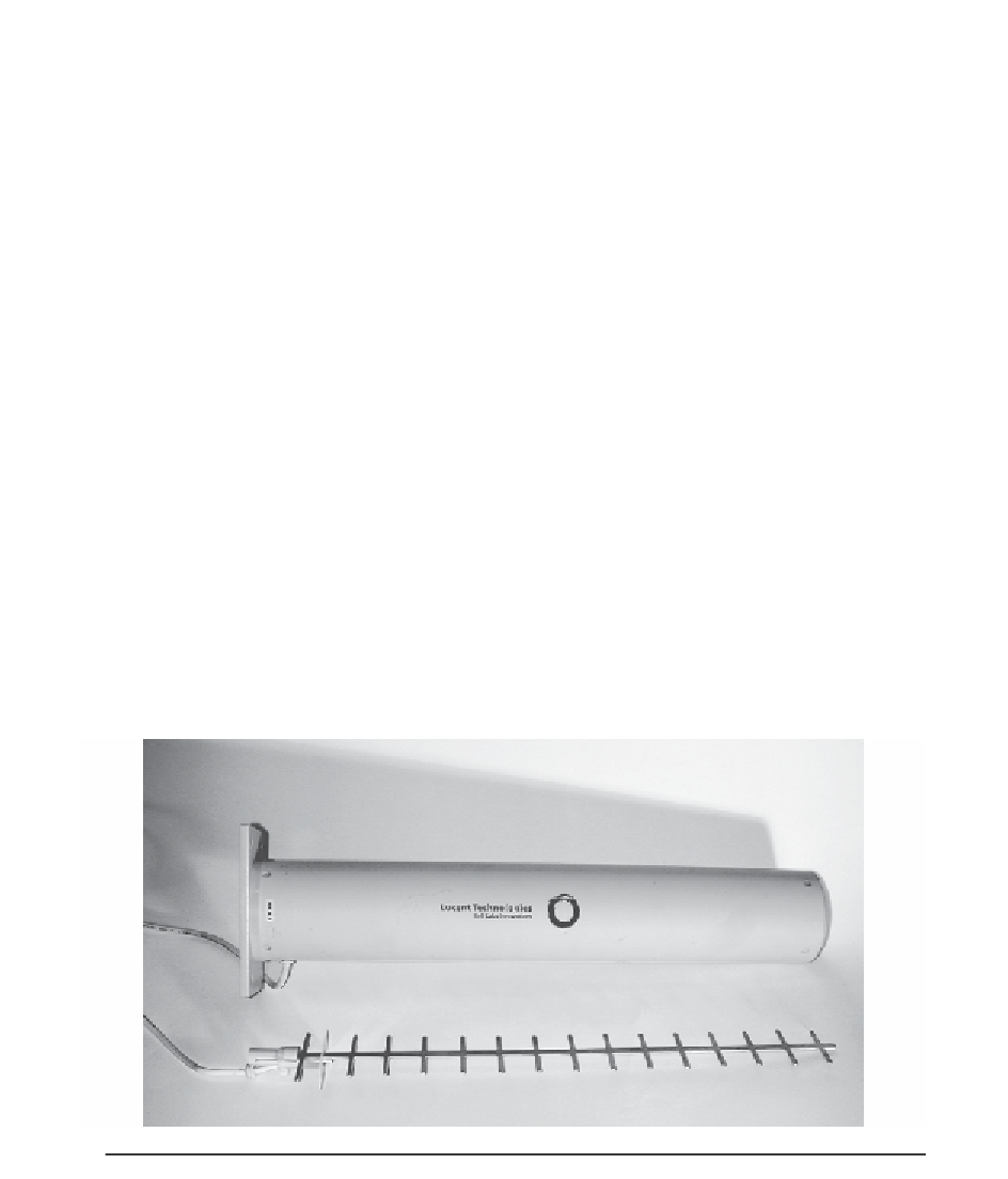
The Yagi antenna (properly the Yagi-Uda Array, so named after its inventors)
consists of an array of parallel conductive elements (Fig. 13.4). The rear-most ele-
ment is called the reflector, followed by the driven element (to which the signal is
applied), and then a series of oddly spaced conductive elements that “point” in the
FIGURE 13.4
Yagi antenna and radome.