Information Technology Reference
In-Depth Information
If your connection required pairings on a different pattern than was wired in
the cable, the result would be a split-pair condition, which causes severe perform-
ance impairment above 1 MHz or so. That is why choosing the correct pattern for
your equipment is so important. Fortunately, virtually all LAN equipment can be
supported on either of the TIA patterns.
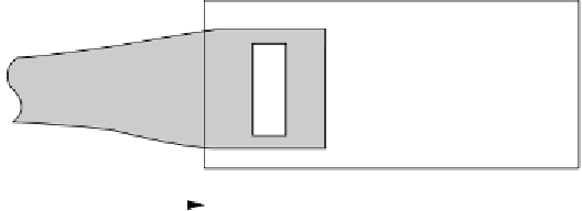
Figure 9.3 shows the recommended dimensions for an optimum modular plug ter-
mination. The dimensions are taken from Annex B of TIA-568-C. Notice that the
crossover of conductor 6 occurs inside the plug, forward of the strain-relief tab. This is
a little different from the standard practice, which places the crossover just outside the
tab. Also notice the length of untwisted wire that exists inside the plug body. It is this
untwist that hampers the performance of the plug in very high frequency environments.
The step-by-step procedure for terminating a cable in a modular plug is as fol-
lows. Refer to Fig. 9.3 and Fig. 9.4. Begin by removing the cable jacket a minimum
of 20 mm (0.8 in) from the end of the conductors.
10 1 mm
(0.4
0.04 in)
Round jacket
Flat portion
4 mm
(0.16 in)
max.
FIGURE 9.3
The recommended dimensions for an optimum modular plug termination. The dimensions are
taken from Annex B of TIA-568-C.
Primary strain relief
1
8
6 mm (0.24 in)
min.
Conductors
bottomed out
FIGURE 9.4
Untwist the pairs back to the jacket, placing the wires of each pair in the proper order, accord-
ing to the color code. Notice that conductor 4 crosses over conductors 5 and 6 inside the
strain relief and terminates at position 6.