Information Technology Reference
In-Depth Information
is data-grade, so that some twist is maintained between the jacks and the 66 block's
clips. This arrangement must not be used for Category 4 or 5 operation, unless it is
certified to those specifications.
Several methods may be used to mount the 66M in a permanent location. Most
commonly, the block may be directly mounted on a backboard. The typical back-
board is a 4
8 sheet of 3/4-in plywood, securely fastened to the wall and painted
an appropriate color, such as battleship gray. The 66-block assembly is actually made
up of two pieces, a front block that contains the contacts and molded side slots, and
a stand-off bracket that mounts to the backboard. The bracket is normally mounted
to the backboard before the 66M is attached. Two slotted, mounting holes are
located on the upper left and lower right corners of the bracket. The slotted arrange-
ment allows the mounting screws to be preinstalled on the backboard before the
bracket is mounted. This two-piece structure, bracket and block, allows easy align-
ment and quick mounting, and facilitates the use of preassembled mounting frames.
After the bracket is mounted, the 66 block is set on top and secured by four clips
that are part of the bracket. Connectorized 66 blocks have the connector mounted to
the bracket, with the front block already attached, and must be installed as a unit.
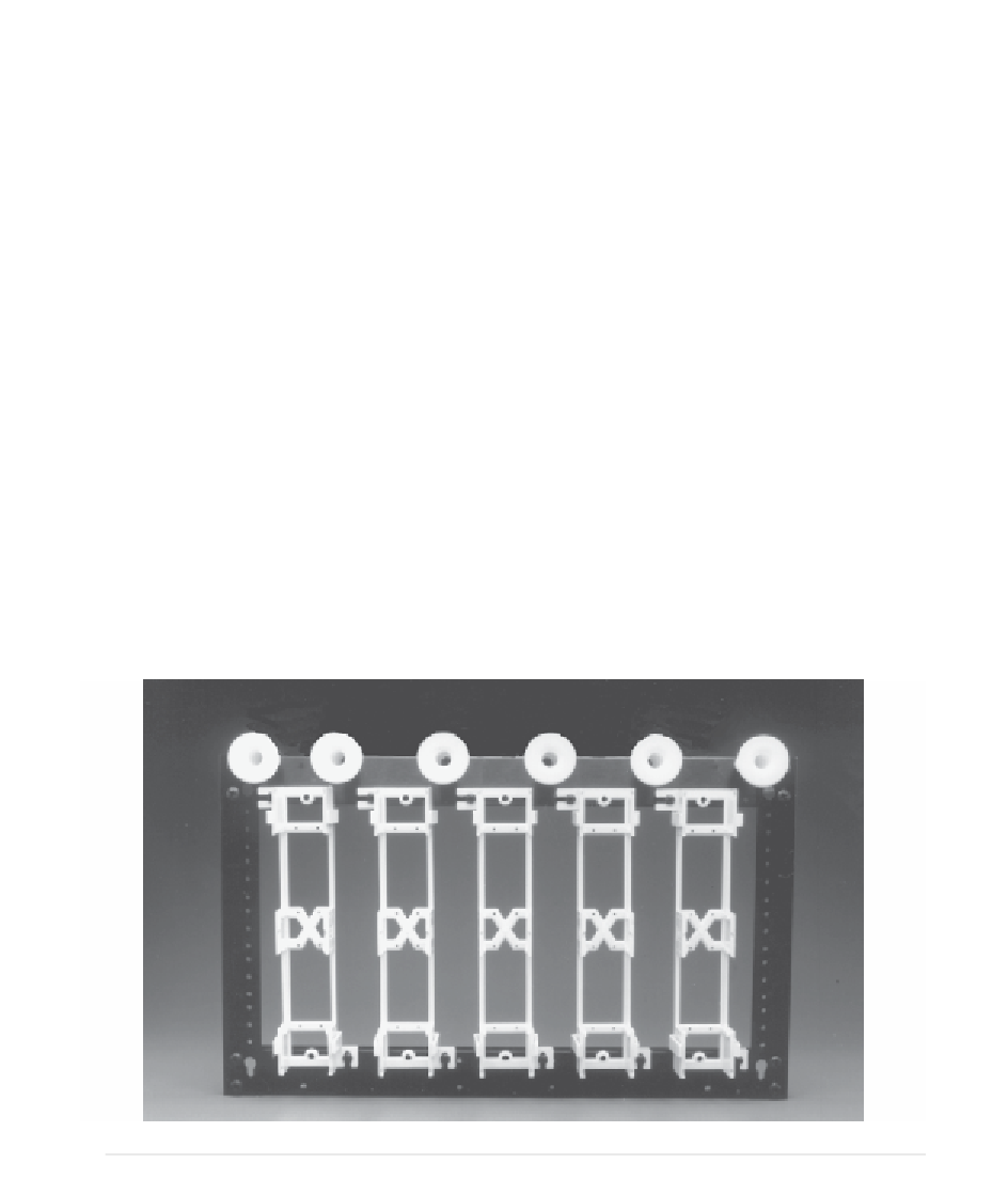
In addition to direct mounting on a backboard, the 66M may be mounted in a
preassembled mounting frame. A typical distribution frame is shown in Fig. 7.8. The
frames are mounted as a unit onto wooden backboards, although some of the
frames may be mounted on standard 19-in rails as well. These frames usually have
FIGURE 7.8
A typical distribution frame for 66 block. (Courtesy of The Siemon Company.)