Graphics Reference
In-Depth Information
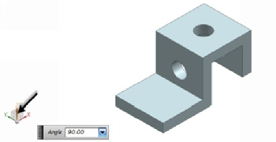
20.
On the bottom-left corner of the graphic window, click the Z-axis of the co-
ordinate system and set the
Angle
value to 90. This changes the view orient-
ation of the model.
21.
Activate the
Hole
command.
22.
On the
Hole Options
dialog, select
Form > Simple
and type-in
10
in the
Diameter
box.
23.
Click on the lower top face to place a point for the hole location. Place one
more point and add dimensions to define the location of the holes. Click
Fin-
ish
on the ribbon.
24.
Click
OK
to complete the hole feature.