Graphics Reference
In-Depth Information
5.
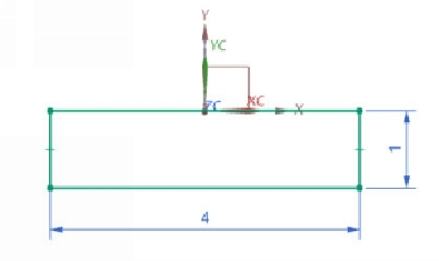
Finish the sketch and change the model orientation to Isometric.
6.
Activate the
Revolve
command (On the ribbon, click
Home > Feature >
Design Feature Drop-down > Revolve
) and click on the sketch.
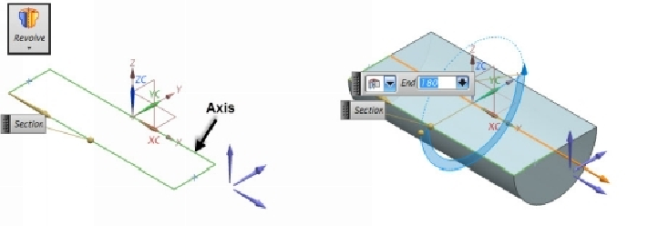
7.
On the
Revolve
dialog, click
Specify Vector
and click on the line passing
through the XC-axis.
8.
On the
Revolve
dialog, under the Limits section, type-in
180
in the
Angle
box below the
End
drop-down. Click
OK
to create the
Revolve
feature.
9.
Activate the
Revolve
command and click on the top face of the part geo-
metry.
10.
Draw the sketch on top face and apply dimensions. Finish the sketch.