Image Processing Reference
In-Depth Information
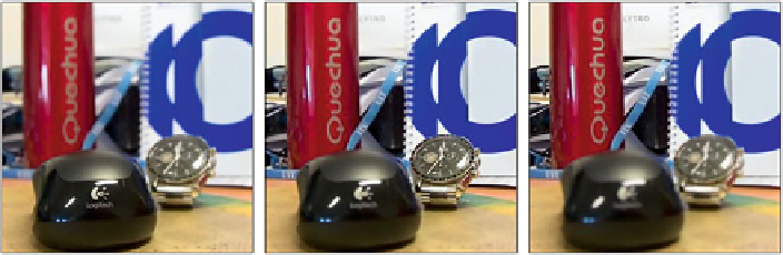
Fig. 3.2 Different focal planes extracted from a 3D holoscopic image
motion parallax. More details on 3D holoscopic imaging can be found in the
Chapter “3D Holoscopic Video Representation and Coding Technology.”
Besides a 3D representation of the visual scene, new degrees of freedom in terms
of content manipulation are also possible with 3DHV, such as changing the plane of
focus or the scene perspective (see Fig.
3.2
).
3.2.2 Multiview Video-Plus-Depth
Recent displays enable a more immersive experience by using more than two
views. Current autostereoscopic displays use from about ten to thirty views to
achieve a 3D effect without requiring the use of glasses. On the other hand, several
emerging applications, like free viewpoint video and free viewpoint TV, require the
availability of a large number of views in the decoder/display side.
The straight forward approach of transmitting all the views to the decoder has a
requirement that grows linearly with the number of used views, both in terms of the
number of used cameras and the bandwidth for transmission or storage space [
11
].
A more efficient representation of the three-dimensional scene can be achieved
by using information about the location of the observed objects in relation to the
cameras
position. For this purpose, a representation of the relative depth of each of
the areas of the image is used. This method is the so-called multiview video-plus-
depth format (MVD) [
11
,
12
]. In MVD, a small number of texture views are used,
combined with the geometric information of the scene, represented by
depth-maps
.
A depth-map contains the distance of each pixel represented in the texture of the
captured view relative to the camera.
In a given acquisition system, the range of depths (
z
min
,
z
max
) is mapped into the
values of each element of the bi-dimensional matrix which corresponds to the
depth-map. For the common case of a representation using 8 bits for each depth
sample, this means that the (
z
min
,
z
max
) range is divided into 256 uniform intervals.
An inverse notation is common, meaning that a value of 0 in the depth map
corresponds to
z
max
, while
z
min
is represented by a sample value of 255. Figure
3.3
represents the texture captured by camera 3 for the Ballet sequence (left) and its
associated depth-map (right).
'