Environmental Engineering Reference
In-Depth Information
FIGURE 13.6
In situ
mixing with a tractor-mounted disk harrow.
of a common breed. The many varieties of
in situ
systems are rarely, if ever, applied
at fixed installations because they are not needed. Normally, a wide variety of wastes
are delivered to a treatment facility
Pit Mixing Methods
. Figure 13.7 shows a typical pit mixing installation at a
TSDF. Most of these installations today are well controlled, using reagent storage
and feeding equipment that can accurately proportion the reagent/waste ratio and
also the water addition, if required. The pit is generally a steel- or concrete-lined
basin with secondary containment. Because it is relatively small, 38 m
3
(50 yd
3
) or
less, and configured to eliminate dead areas that the backhoe bucket can't get into,
it can do a good mixing job with most waste streams. The nature of the backhoe
allows the method to work well with debris and other large particles that could not
be handled with a mechanical mixer-based system. Pit mixing is a large-batch process
that is an efficient method for TSDFs where each waste load, typically 20 tons,
coming to the stabilization plant may require a different formulation. A continuous
mixer-based system is less practical for such sudden changes in waste characteristics
with each waste load delivery. While a batch, mechanical mixer-based setup could
be used in the same way, it is not practical to use a pugmill or other mixer to make
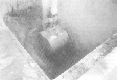
FIGURE 13.7
Ex situ
pit mixing at a TSDF.

Search WWH ::

Custom Search