Environmental Engineering Reference
In-Depth Information
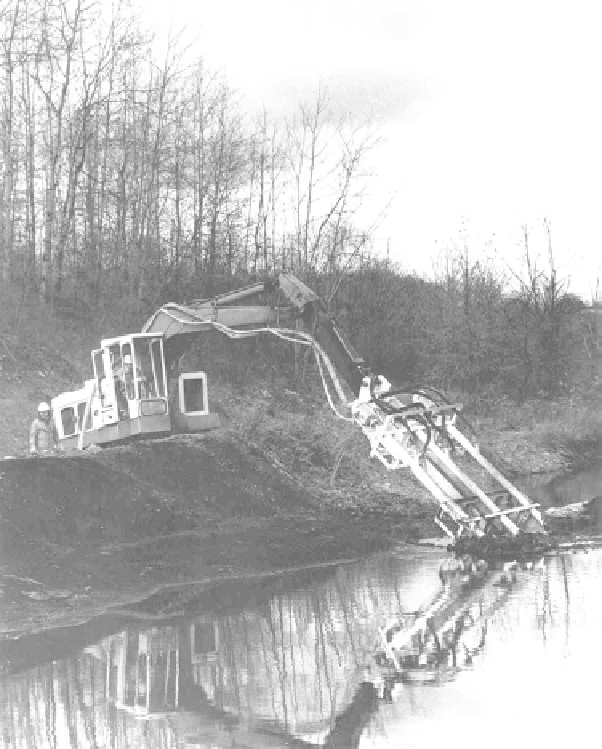
FIGURE 13.3
In situ
mixing with backhoe-mounted rake injector.
a well-controlled process and was used mainly for solidification only. Later, pneu-
matic or hydraulic injectors were added to the backhoe arm to improve reagent
distribution and control, and rake-type devices or high-energy mixers to improve
mixing. One such device is shown in Figure 13.3.
Drilling/Augering/Jetting/Trenching Methods
. Most recently, massive earth drill-
ing and foundation construction equipment has been modified to allow well-con-
trolled reagent injection and mixing to be performed to great depths. One such
system is shown schematically in Figure 13.4 and in actual operation in Figure 13.5.
A S/S reagent slurry is pumped through a drilling assembly, consisting of a vertical,
hollow bar called a “kelly bar” and a set of hollow auger blades, into the soil or
sludge as the assembly is rotated down through the contaminated media. Very high
torque (up to 400 kJ or 300,000 ft/lb) produces a well-mixed, treated column of
waste at depths up to 100 ft or more, with diameters of up to 14 ft. Overlapping,
consecutive columns are positioned to cover the entire volume of waste. A major
Search WWH ::

Custom Search