Information Technology Reference
In-Depth Information
⎧
min
l
P
≤
P
≤
P
i
i
i
,
⎪
⎨
u
k
l
k
(7)
P
∈
P
≤
P
≤
P
,
k
=
2
,
,
z
…
i
i
,
−
1
i
i
,
i
⎪
⎩
u
max
P
≤
P
≤
P
i
,
z
i
i
i
l
/
u
,
is the lower/upper bound of the
k
th
prohibited zone of unit
i
and
z
i
is the
i
th
prohibited zone.
where
P
k
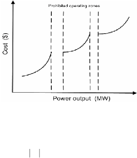
Fig. 5.
Prohibited operating zones
(iv) Line flow constraint
Line flow constraints can be expressed as follows:
max
Lf
≤
Lf
,
i
=
1
..
N
(8)
i
i
L
max
where
Lf
is the allowable maximum flow of transmis-
sion line
i
(line capacity), and
N
L
is the number of transmission lines subject to line
capacity constraints.
Lf
is the MW line flow.
i
i
(v) Ramp-rate limits constraint
To avoid excessive thermal stresses on the boiler and combustion equipments, the rate
of change in the output power of each thermal unit must not exceed a certain rate dur-
ing increasing or decreasing the power output of each unit. This constraint can be
formulated as follows:
min
o
max
o
max(
P
,
P
−
DR
)
≤
P
≤
min(
P
,
P
+
UR
)
(9)
i
i
i
i
i
i
i
o
P
is the previous output power. UR
i
is the upramp limit of the
i
th
generato-
rand and DR
i
is the downramp limit of the
i
th
generator.
where
Search WWH ::

Custom Search