Information Technology Reference
In-Depth Information
20000
19100
17500
16198
15712
15000
15488
14384
12500
10000
0
1
2
3
4
Beam S pacing (m)
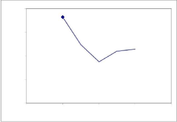
Fig. 4.
Variation of weight different beam spacing
that are practically preferred. It is apparent from Figure 4 that 2-m spacing is the op-
timum spacing among the values considered. Consequently it should be pointed out
that consideration of beam spacing as an additional design variable in addition to steel
section designations that are selected for member groups in the design of grillage sys-
tems would yield better results.
5 Optimum Geometry Design of Geodesic Domes
Domes are lightweight and cost effective structures that are used to cover large areas
such as exhibition halls, stadium and concert halls. They provide a completely unob-
structed inner space and they are economical in terms of materials compared to the
more conventional forms of structures as explained in Makowski [30]. They consist of
one or more layers of elements that are arched in all directions. These structures are
sometimes called braced domes which is a term used for single-layer spherical space
structures that are usually used to cover large spans up to about 150m and have typi-
cally a very small weight, around 15-20 kg/m
2
.
The geodesic dome shown in Fig. 5 is a commonly used form as a structural sys-
tem. It has relatively simple geometry. In this dome all the structural data related with
the geometry of the dome can be obtained automatically provided that the diameter
D
,
the total number of rings
n
r
and the height of the crown
h
in the dome are known. It is
worthwhile to mention that rings in the dome are arranged in such a way that the dis-
tance between them on the meridian line is equal. The details of this automatic data
generation are given in [31].


Search WWH ::

Custom Search