Biology Reference
In-Depth Information
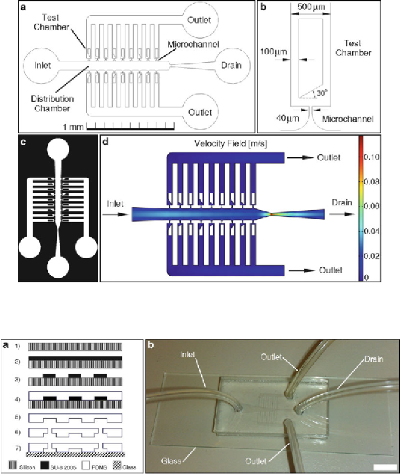
Fig. 1
Overall design of the LOC. (
a
) Schematic. (
b
) Detailed layout of a microchannel and test chamber.
(
c
) Photomask. (
d
) Velocity fl uid fi eld simulation of the microfl uidic platform
Fig. 2
(
a
) Microfl uidic platform fabrication: (
1
) Silicon wafer cleaning, (
2
) SU-8 2035 photoresist spin-coating,
(
3
) Photolithographic patterning and photoresist development, (
4
) PDMS pouring and curing, (
5
) PDMS layer
detachment, (
6
) Microfl uidic access drilling, (
7
) PDMS-glass bonding. (
b
) Fabricated LOC. Scale bar = 1 mm.
Reproduced from [
11
] with permission from IOP Publishing Limited
overall design of the microfl uidic network might need to be
revisited. Figure
2
shows the microfl uidics simulation for the
current platform which ensures a uniform distribution of pol-
len grains over the microchannel entrances (
see
Note 6
).
Search WWH ::

Custom Search