Biology Reference
In-Depth Information
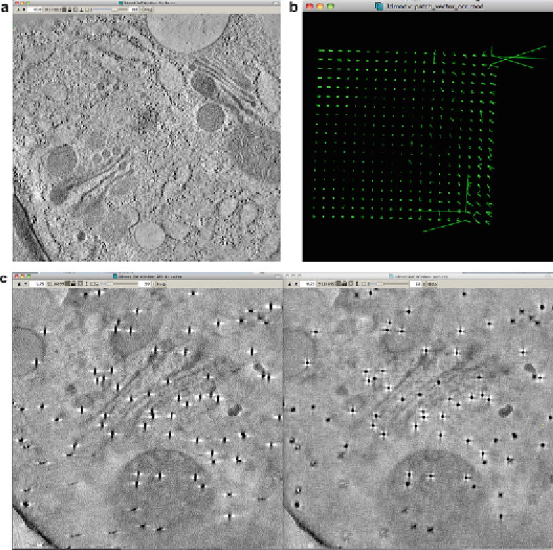
Fig. 2
(
a
) A slice image of the axis A tomogram from the section in Fig.
1
. (
b
) Patch vector model generated for
combining the axis A and axis B tomograms. There are several abnormally long vectors in the
upper right corner
and in the
lower right corner
. Combination can restart after deleting the abnormal vectors. (
c
) Slice images
showing fi ducial particles of a single axis tomogram (
left
) and a dual axis tomogram after combination (
right
)
automatically. In the Setup tab, information for starting tomo-
gram combination is given. Usually the axis B tomogram is
matched to the axis A tomogram and is chosen accordingly in
the “Tomogram Matching Relationship” box. Indicate that
fi ducials are present on both sides of the section in the
“Solvematch Parameters” box. In the “Patch Parameters for
Refi ning Alignment” box, select “Medium Patches.” If the
tomogram has large areas which contain no structural infor-
mation for matching the two tomograms, it is advantageous to
use the “patch region” model. For example, large vacuoles or
thick cell wall areas do not have features that can be utilized
for fi nding corresponding volumes in the two tomograms
Search WWH ::

Custom Search