Biology Reference
In-Depth Information
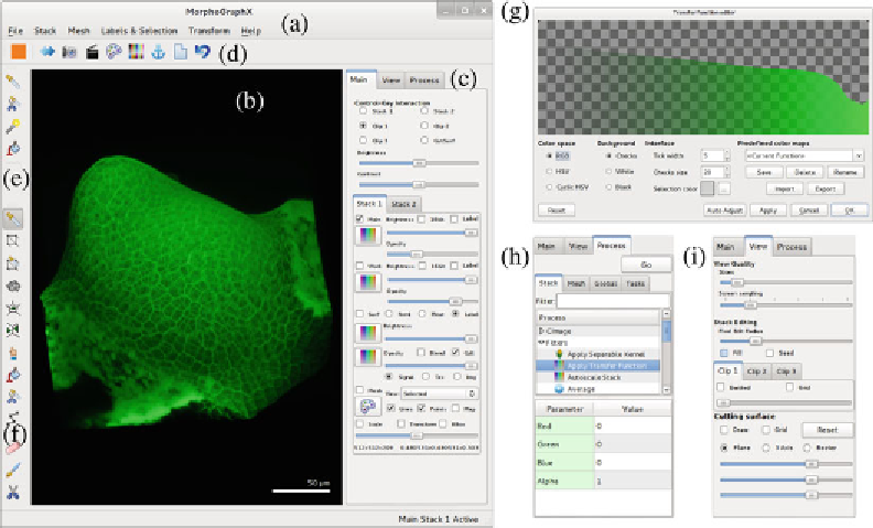
Fig. 1
MorphoGraphX main window: (
a
) menu bar; (
b
) visualization window; (
c
) tab panel; (
d
) global toolbar;
(
e
) volume toolbar; (
f
) mesh toolbar; (
g
) transfer function dialog box; (
h
) “Process” tab; (
i
) “View” tab. The
visualization panel shows the loaded stack
A
mesh
consists of vertices connected into triangles to defi ne a
surface. MorphoGraphX can perform image processing operations
on this curved surface, with each vertex of the mesh corresponding
to a pixel in a fl at 2D image. It is also possible to modify the struc-
ture of the mesh, for example, by subdividing triangles or deleting
vertices.
Each stack is associated with a single mesh. They share the
same reference system and therefore cannot be displaced relative to
each other. However, MorphoGraphX does allow two stacks and
their associated meshes to be loaded at the same time. These stacks
have their own coordinate systems and therefore can be positioned
independently.
Any modifi cation that does not require user interaction is
achieved through the use of
processes
. The processes are grouped in
three categories: (1)
stack processes
, which modify only the stacks
and their positions; (2)
mesh processes
, which modify only the
meshes (surfaces) and their properties; and (3)
global processes
,
which may modify anything. The list of processes is located in the
interface on the “Process” tab (Fig.
1h
). In the box below the
process list, the relevant parameters are displayed for the selected
process. Once the parameters are entered, the process is executed
either by pressing the “Go” button on the top-left corner of the
tab or by double-clicking on the process name. The result of a
process is either a modifi cation of the state (visualization, fi le saved,
etc.) or an error which will appear in a dialog box.
Search WWH ::

Custom Search