Biomedical Engineering Reference
In-Depth Information
N under
pressure
2
Ultrafilter
Protein molecule
Lower molecular
weight molecule
Porous support
for filter
Effluent
(a)
(b)
Photo courtesy of Elga Ltd
(c)
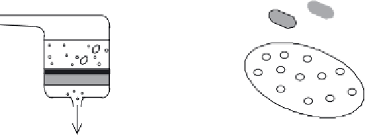
Figure 6.6
Ultrafi ltration separates molecules based on size and shape. (a) Diagrammatic representation
of a typical laboratory-scale ultrafi ltration system. The sample (e.g. crude protein solution) is placed in the
ultrafi ltration chamber, where it sits directly above the ultrafi lter membrane. The membrane, in turn, sits on a
macroporous support to provide it with mechanical strength. Pressure is then applied (usually in the form of
an inert gas), as shown. Molecules larger than the pore diameter (e.g. large proteins) are retained on the up-
stream side of the ultrafi lter membrane. However, smaller molecules (particularly water molecules) are easily
forced through the pores, thus effectively concentrating the protein solution (see also (b)). Membranes that
display different pore sizes, i.e. have different molecular mass cut-off points, can be manufactured. (c) Pho-
tographic representation of an industrial-scale ultrafi ltration system (photograph courtesy of Elga Ltd, UK)
Large-scale ultrafi ltration systems invariably employ cartridge-type fi lters (
Figure
6.6c). This
allows a large fi ltration surface area to be accommodated in a compact area. Concentration po-
larization is avoided by allowing the incoming liquid to fl ow across the membrane surface at right
angles, i.e. tangential fl ow. The ultrafi ltration membrane may be pleated, with subsequent joining
of the two ends to form a cylindrical cartridge. Alternatively, the membrane may be laid on a
spacer mesh and this may then be wrapped spirally around a central collection tube, into which
the fi ltrate can fl ow.


Search WWH ::

Custom Search