Chemistry Reference
In-Depth Information
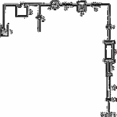
Fig. 12.9
Scheme of the column packing apparatus. 1, reservoir (methanol or
water); 2, pump; 3, valve; 4, manometer; 5, capillary; 6, pulse
dampener; 7, valve, 8; slurry reservoir; 9, precolumn; 10, column; 11,
plug of wool in low dead volume connector
Source: Reproduced with permission from Elsevier Science [11]
homogenised by sonication. The column and precolumn are filled with
tetrachloromethane in order to prevent inclusion of air bubbles in the packed bed. The
slurry reservoir is filled with the slurry and thereafter methanol is added to remove all air
up to the shut off valve. When the pump and dampers have been filled with methanol, the
slurry reservoir is connected to the pump (with valve 7 closed). The apparatus is
pressurised with methanol up to 400bar. Thereafter, valve 7 is opened and the slurry is
forced into the column. The packed bed is settled by flushing 200ml of methanol and
200ml of water through the column at maximum pressure.
Glass columns can also be slurry packed by this method when the pressure across the
column is kept below 60bar. A short glass column (100 ×4.0mm) packed with Zipax
SAX was used as a concentrator column.
T
he void volume of the separator column (V
m
) is estimated from the retention volume
of water. The capacity ratio k is calculated from the equation
k
=(V
R
−V
M
)/V
m
, where V
R
and V
M
are the retention volumes of the solute and water respectively in the separator-
suppressor column combination. The
k
values are independent of sample size (50-200µL
of solutions of 10mg L
−1
nitrate and 10mg L
−1
sulphate), only slightly dependent on the
eluent flow rate (1.5-4.5ml min
−1
), and reproducible within 3%.
Search WWH ::

Custom Search