Chemistry Reference
In-Depth Information
0.01µg L
−1
were detected by this method.
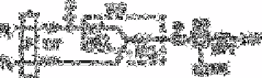
Fig. 2.31
Schematic flow diagram for the determination of nitrite R
1
,
p-
aminoacetophenone solution (5g plus 10ml conc, hydrochloric acid
diluted to 500ml diluted to 40ml to 1L); R
2
,
m
-phenylenediamine
solution (13.8g
m
-phenylene dihydrochloride, diluted in 500ml water,
diluted 40ml to 1L); P, double
plunger
micro pump (1.7ml min
−1
);
DT, damping coil (0.5mm id×20m); S, loop valve sample injector
(sample volume 650µL); WB, water bath 30°C); MC 1, mixing coil
(1mm id×150cm); MC 2, mixing coil (1 mm id×100cm); F, line
filter; SP, spectrophotometer with flow cell (light path 10mm, 8µL);
RE, recorder, BPT, back pressure coil (0.5mm id×5m); W, water
Source: Reproduced with permission from Elsevier Science [525]
Motomizu
et al.
[510] have also performed a flow injection analysis-spectrophotometric
determination of traces of nitrite in water based on the nitrosation reaction with
N,N
′
-
bis
(2-hydroxypropyl) aniline.
Nakashima
et al.
[525] have described a spectrophotometric determination of nitrite at
the µg L
−1
level in non saline waters by flow injection analysis. The limit of detection is
0.2µg L
−1
for sample injections of 650µL. The sampling rate is about 30 per h and the
relative standard deviation is less than 1.3%.
A diagram of the flow system is shown in Fig. 2.31. The absorbance was measured
with a Shimadiu double-beam spectrophotometer UV-140-02 with a 1−cm flow cell
(8µL) and recorded by a Rikadenki R022 recorder. A double-plunger micro pump
(Kyowa Seimitzu KHU-W-52) is used. The sample solution (650µL) is injected by a 6-
way injection valve into the reagent R
1
stream. The water bath, in which the mixing coils
was heated to accelerate the reactions. Temperature is controlled by a Taiyo Thermo
Minder Jr-10. The flow lines are made from polytetrafluoro-ethylene (PTFE) tubing 1mm
and 0.5mm id). The mixing coils (1mm id) MC1 and MC
2
are optimally 1.5 and 1.0m
long, respectively, and are wound around plastic rods (6mm od). The damping coils
(0.5mm id) are 20m long, to cancel the pulse from the reciprocal pump. The back-
pressure tubing (0.5mm id) are 5m long, to prevent formation of bubbles.
T
he reagent solutions R
1
and R
2
are prepared by diluting 40ml of the appropriate stock
solutions to 1L; the pH of R1 is adjusted to 1.3 and the pH of R
2
to 2.4. Both reagent
solutions give the same response for three months (maximum period tested) if kept in a
refrigerator when not in use.
T
he flow rates of R
1
and R
2
are 1.7ml min
−
1
each. Sample solutions are filtered
through a 0.45µm Millipore filter. From the sample loop, 650µL of sample solution is
injected into the reagent R, stream. Peak heights are measured at 456nm against water as
reference. The concentration of nitrite is evaluated from the peak heights by using a
Search WWH ::

Custom Search