Chemistry Reference
In-Depth Information
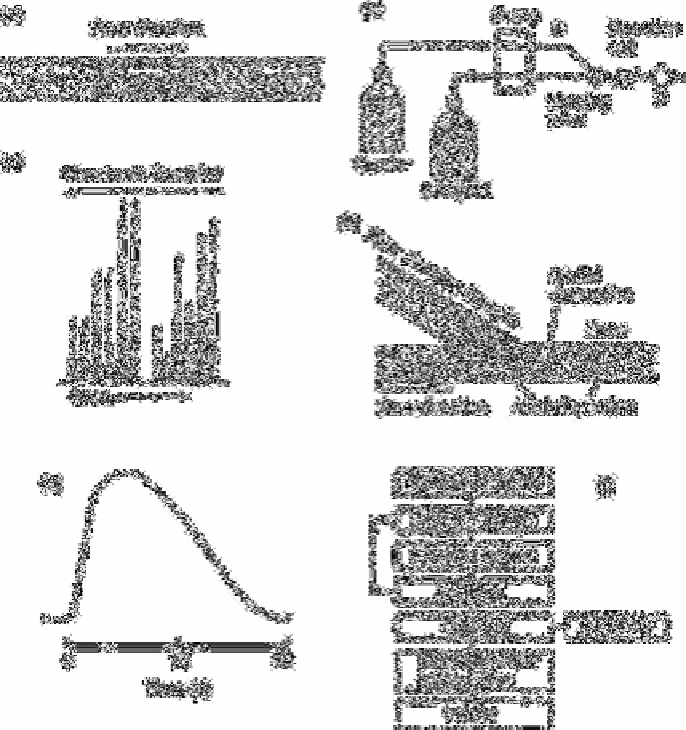
Fig. 1.1
(a) Schematic diagram of the flow pattern in an FIA system directly
after injection of sample, (b) Simple FIA system for one reagent; S
denotes the sample injection site and D is the flow-through detector,
(c) Typical FIA peaks (detector output signals), (d) Radial and axial
dispersion in an injected sample plug, (e) Rapid scan of an FIA curve,
(f) Configuration of an FIA system.
Source: Own files
Waste waters:
chloride, free cyanide and total cyanide.
Sewage effluents:
phosphate.
Flow injection analysis (FIA) is a rapidly growing analytical technique. Since the
introduction of the original concept by Ruzicka and Hansen [1] in 1975, about 1000
papers have been published.

Search WWH ::

Custom Search