Graphics Reference
In-Depth Information
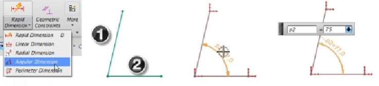
This command creates an angle dimension between two selected elements. Activate this
command and select the elements. Next, move the pointer and position the dimension.
Type-in a value and press Enter to update the dimension.
Over-constrained Sketch
When creating sketches for a part, NX will not allow you to over-constrain the geometry.
The term 'over-constrain' means adding more dimensions than required. The following
figure shows a fully constrained sketch. If you add another dimension to this sketch (e.g.
diagonal dimension), the
Update Sketch
message pops up. It shows that the dimension
over constrains the sketch. If, you click OK, all the dimensions in the sketch will become
red.
Now, you have to make one of the dimensions as a Reference dimension. Click on the diag-
onal dimension and select
Convert to Reference
on the contextual toolbar. The
Convert
Dimension to Reference
message appears. Click
OK
to convert the dimension to referen-
ce. The reference dimension will be in brown color. Now, if you change the value of the
width, the reference dimension along the diagonal updates, automatically. Also, note that
the dimensions, which are initially created, will be driving dimensions, whereas the dimen-
sions created after fully defining the sketch are driven dimensions.