Biomedical Engineering Reference
In-Depth Information
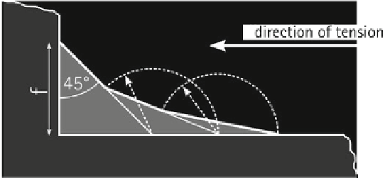
Fig. 7
Construction of tensile triangles according to Mattheck [
30
]
Ta b l e 3
Normalized stress in rounding compared to tensile triangle
Radius 0.5 (mm)
Radius 1 (mm)
Chamfer 0.5 (mm)
Chamfer 1 (mm)
1.21
1.11
1.17
1.32
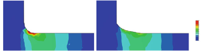
Fig. 8
Stress distribution in a rounding with radius of 0.5mm (
left
) and a rounding shaped with
tensile triangles with a basic length of 0.5mm (
right
)
subsequent triangle begins in the middle of the previous one and extends in the
direction of tension. In most cases, three triangles are sufficient. Obtuse corners are
rounded off with radii, except the corner of the first triangle.
This method is described in [
30
] for shape improvements in the direction of
tension; here we applied and tested it for bending dominated problems. Therefore,
a 1mm thick cantilever beam with elastic material properties was modeled. The
thickness is unchanged, but corners in width are modified. One 90
ⓦ
corner was
=
.
shaped with tensile triangles, basic length of f
5mm, and compared with corners
formed with radii of 0.5mm and 1mm, as well as corners with chamfers of 0.5mm
and 1mm. The beam tip was deflected. Maximal von Mises stress was determined
and normalized to the tensile triangles model as given in Table
3
. Further, the stress
distribution of the tensile triangles is displayed in comparison with the 0.5mm radius
in Fig.
8
.
With tensile triangles, the maximal stress is reduced about 21% in comparison
with a radius of 0.5mm as stated in Table
3
. Also, a much smoother stress distribution
is obtained, as can be seen in Fig.
8
. These results are promising: the method of
0