Biomedical Engineering Reference
In-Depth Information
(a)
(b)
(c)
(d)
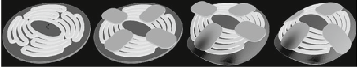
Fig. 2
Modeling of flat scaffold:
a
Positioning of flat scaffold on plate, nodes A are constrained in
y-direction and node B is constraint in x-direction;
b
positioning of thumbs onto scaffold;
c
and
d
deforming flat scaffold into heart curvature in two steps
(a)
(b)
(e)
(c)
(d)
Fig. 3
Modeling of preformed scaffold:
a
positioning of sutures onto flat scaffold;
b
preforming
of myocardium with sutures;
c
and
d
deforming flat scaffold into preformed state;
e
assembling of
orphan-meshes of scaffold, myocardium and sutures in preformed state
Preformed scaffolds can be designed with CAD
2
-programs and imported into
finite element (FE) software. However, it is costly to mesh curved, complex geome-
tries with hexahedral elements; furthermore, positioning of sutures is challenging.
Therefore, another method was chosen. In flat state, sutures were positioned on the
scaffold according to their locations in surgeries (Fig.
3
a). Sutures were simplified as
half cylinders. They restrain their position relative to the myocardium during heart
movement. The myocardiumwith sutures was deformed into the preformed state (see
Table
1
) as shown in Fig.
3
b. In the second step, the scaffold was also deformed into
the preformed shape (Fig.
3
c, d). The preformedmeshes are imported as orphan-mesh
into a second model (Fig.
3
e). Orphan-meshes contain no history data; therefore, they
are stress free, comparable to a preformed structure after heat treatment. The heart
movement of the preformed myocardium is modeled using the displacements in
Eqs. (
1
-
3
), but it is necessary to calculate the displacement differences from one
curvature state to the other.
2
Computer Aided Design.